The density/area method is a widely used sprinkler design method in NFPA 13. Outside of storage occupancies it applies to building types such as offices, hotels, hospitals, schools, retail and manufacturing. The two parameters look simple: water flow per unit area and the total area of simultaneously activating sprinklers. But the question "which density with which area?" can make or break a project. This guide walks through the NFPA 13-2025 tables, practical selection rules, and design mistakes to avoid.
The Logic: What Is Being Calculated?
The essence of the density/area approach: when a fire occurs, the sprinkler system must deliver enough water flow to control that fire over an area large enough to matter. The product of these two variables gives the minimum water demand:
Qmin = Density × Area of Operation
For example, with 0.10 gpm/ft² design density and 1500 ft² area of operation: 0.10 × 1500 = 150 gpm (about 570 L/min). Hose stream allowance is then added to reach the system's total minimum water demand.
Two critical points before moving on: (1) density is only the lower limit — a system must meet it, can exceed it. (2) area of operation isn't arbitrarily inflated; unnecessary water demand grows pumps and piping.
Hazard Classes and Typical Values
Per NFPA 13, every building falls into a hazard class based on fire load and burning characteristics. The values below are from NFPA 13-2025 Table 19.2.3.1.1, with typical occupancies from Annex A.4.3:
| Hazard Class | Density (gpm/ft²) | Density (mm/min) | Design Area (ft²) | Typical Application |
|---|---|---|---|---|
| Light Hazard | 0.10 | 4.1 | 1500 | Hotel room, residential, office, hospital |
| Ordinary Hazard Gr. 1 | 0.15 | 6.1 | 1500 | Canneries, bakeries, laundries, electronic plants |
| Ordinary Hazard Gr. 2 | 0.20 | 8.1 | 1500 | Parking garages, printing, library large stack rooms, metal working |
| Extra Hazard Gr. 1 | 0.30 | 12.2 | 2500 | Combustible hydraulic fluid use areas, die casting, sawmills, plywood and particleboard manufacturing |
| Extra Hazard Gr. 2 | 0.40 | 16.3 | 2500 | Flammable liquids spraying (paint booths), solvent cleaning, varnish and paint dipping |
In NFPA 13-2025 this is a single-point table; there is no longer a density/area curve to choose from. The area changes only through the standard's own adjustment rules (3000 ft² / 280 m² where there are unsprinklered combustible concealed spaces, using the table's second, lower-density column, e.g. LH 0.07, OH1 0.12, OH2 0.17, EH1 0.28, EH2 0.38 gpm/ft², 19.2.3.1.5).
Area of Operation Adjustment Factors
The 1500 ft² (140 m²) from the table — 2500 ft² (230 m²) for Extra Hazard — is the "baseline" operation area. In actual design, these conditions increase the area:
- High ceiling (> 30 ft / 9.1 m): OH1 +30% area; OH2 minimum density 0.37 gpm/ft² (15.1 mm/min) between 30 and 40 ft and 0.45 gpm/ft² (18.3 mm/min) with a 30% larger design area above 40 ft (no area increase with K25.2 (K360) or larger extended-coverage sprinklers); Extra Hazard moves to a minimum density of 0.45 gpm/ft² (18.3 mm/min) with the Table area (19.2.3.2.5.2)
- Unheated spaces: the 30% increase below applies when the freezing risk leads to a dry pipe system
- Dry pipe and double interlock pre-action systems: +30% area (19.2.3.2.6)
- Sloped ceiling (> 2 in 12): +30% area for unobstructed construction, or one of the other options of 19.2.3.2.4
The area can be decreased under these conditions:
- Quick response (QR) sprinklers: wet system only, LH or OH, ceiling no higher than 20 ft (6.1 m), no unprotected ceiling pockets over 32 ft² (3.0 m²) and no unprotected areas above cloud ceilings; the reduction is 40% up to a 10 ft (3 m) ceiling and falls with ceiling height to 25% at 20 ft: y = −3x/2 + 55 (x in feet; in SI y = −4.8x + 54.6, x in metres) (19.2.3.2.3.1, Figure 19.2.3.2.3.1). The design area never holds fewer than five sprinklers (19.2.3.2.3.2), and quick-response sprinklers are not permitted for Extra Hazard under this method (19.2.3.2.2.2)
- Extra Hazard with high-temperature or K11.2 (K160) and larger sprinklers: with a ceiling of 30 ft (9.1 m) or less the area may be reduced by 25%, but not below 2000 ft² (185 m²); the reduction is applied only once (19.2.3.2.7)
Order of application: multiple adjustments are compounded on the area originally selected from the Table, so a dry pipe system with a ceiling slope over 2 in 12 gives 1.30 × 1.30 = 1.69 times the area. The unsprinklered combustible concealed space rule (19.2.3.1.5) is applied after all other modifications (19.2.3.2.8).
These adjustments are the mechanisms of good engineering, not arbitrary tweaks.
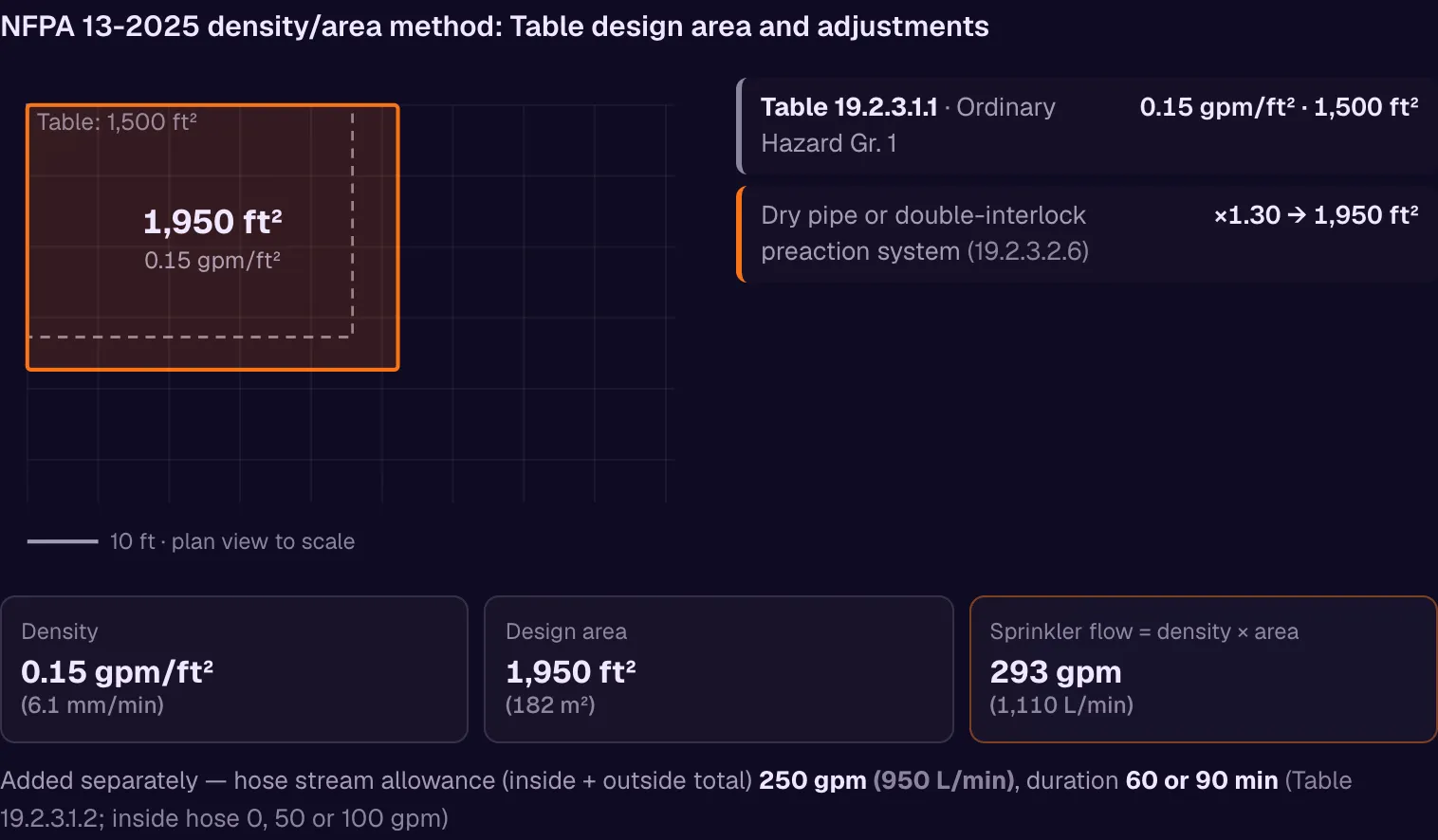
Worked Example: Ordinary Hazard Group 1, Step by Step
This example uses nothing but the Ordinary Hazard Gr. 1 row of the table above — 0.15 gpm/ft² (6.1 mm/min) over a 1500 ft² operation area — for a heated, flat-ceilinged cannery on a wet pipe system (canneries are an OH1 example in Annex A.4.3.3.1). Because none of the adjustment triggers apply (ceiling below 30 ft, wet pipe, flat ceiling) and standard response sprinklers are used, the design area stays at its baseline value.
| Step | Input | Calculation | Result |
|---|---|---|---|
| 1. Density | Table row: Ordinary Hazard Gr. 1 | — | 0.15 gpm/ft² (6.1 mm/min) |
| 2. Area of operation | Table row: Ordinary Hazard Gr. 1, no adjustment | 1500 × 1.00 | 1500 ft² |
| 3. Sprinkler flow | Qmin = Density × Area | 0.15 × 1500 | 225 gpm (~850 L/min) |
| 4. Hose stream allowance | Ordinary Hazard | +250 gpm | 250 gpm (~950 L/min) |
| 5. Total system flow | Sprinkler + hose | 225 + 250 | 475 gpm (~1,800 L/min) |
| 6. Duration | Ordinary Hazard, 60-90 min | — | 60 min (lower value, only under 19.2.3.1.3) |
| 7. Minimum water tank | Total flow × duration | 475 × 60 | ~28,500 gal (~108 m³) |
Metric cross-check. The same table row gives the SI pair 6.1 mm/min over 140 m²: 6.1 × 140 = 854 L/min, within 1% of the 225 gpm (852 L/min) from step 3 — a quick way to catch a unit slip before it reaches the pump schedule.
What moves the answer. Only steps 2 and 6 are discretionary here. If the same plant had a ceiling above 30 ft or ran as a dry pipe system, step 2 would become 1500 × 1.30 = 1950 ft² and the sprinkler flow would rise to 0.15 × 1950 = 293 gpm. If the 90-minute Ordinary Hazard duration is used instead of 60 (the lower value is only acceptable under the supervision conditions of 19.2.3.1.3), step 7 becomes 475 × 90 = ~42,750 gal (~162 m³) — half again as much stored water for exactly the same density.
Example 1: 120-Room Hotel (Light Hazard)
Project: 3-story, 120-room hotel, total protected area 4,800 m². Ceiling height 9.2 ft (2.8 m). QR sprinklers installed.
Class: Light Hazard. Baseline density 0.10 gpm/ft², baseline area 1500 ft².
Adjustment: with a wet system, QR sprinklers and a 9.2 ft ceiling, the ceiling is below 10 ft, so Figure 19.2.3.2.3.1 permits a 40% area reduction: 1500 × 0.60 = 900 ft². This example takes a cautious 25% instead: 1500 × 0.75 = 1125 ft². The reduction is a permission, not a requirement; the unreduced 1500 ft² is equally valid.
Calculation:
- Sprinkler flow: 0.10 × 1125 ≈ 113 gpm (~430 L/min)
- Hose stream allowance (Light Hazard): 100 gpm (~380 L/min)
- Total system flow: ~213 gpm (~810 L/min)
- Duration: 30 min for Light Hazard (NFPA 13-2025 Table 19.2.3.1.2)
- Minimum water tank: 213 × 30 = ~6,400 gal (~24 m³) (without the reduction: (150 + 100) × 30 = 7,500 gal, ~29 m³)
Example 2: Print Shop (Ordinary Hazard Gr. 2)
Project: 2,500 m² print shop with paper stock, ceiling 7 m (23 ft); standard response sprinklers (the QR area reduction cannot be used above a 20 ft ceiling anyway).
Class: Ordinary Hazard Group 2 (printing, Annex A.4.3.3.2). Baseline density 0.20 gpm/ft², baseline area 1500 ft².
Adjustment: the ceiling is below 30 ft, so 19.2.3.2.5.2 does not apply; with a wet system and flat ceiling the area stays at 1500 ft². As a dry pipe system it would become 1500 × 1.30 = 1950 ft².
Calculation:
- Sprinkler flow: 0.20 × 1500 = 300 gpm (~1,130 L/min)
- Hose stream allowance (OH): 250 gpm (~950 L/min)
- Total: ~550 gpm (~2,080 L/min)
- Duration: 60 or 90 min for OH (Table 19.2.3.1.2; the lower value only under the supervision conditions of 19.2.3.1.3); 90 min here
- Minimum water tank: 550 × 90 = ~49,500 gal (~187 m³)
Both examples cover buildings of 2500-4800 m², yet total flow differs by about 2.5× and tank volume by 7-8×. Misclassifying hazard means significantly over- or undersizing pumps and tanks.
Mistakes to Avoid
Mistake 1: Treating every building as "Ordinary Hazard"
Residential projects are sometimes calculated as Ordinary Hazard Group 1 "just in case." But Annex A.4.3.2 lists residential occupancies among the Light Hazard examples. This mistake increases the sprinkler water demand by 50% (0.15 instead of 0.10 gpm/ft² over the same 1500 ft²). The standard does not ask for it, and the pumps and tanks grow accordingly.
Mistake 2: Confusing commodity class with building class
"There's plastic here, let's make it Extra Hazard Group 2" is a misreflex. The building's use/occupancy class and the stored commodity are two distinct concepts. A manufacturing facility processing plastic can still be OH-2 (plastics fabrication is an OH2 example in Annex A.4.3.3.2), and stored plastics are protected under the storage chapters; Extra Hazard requires the process itself to have a high fire load (flammable liquid spraying, solvent cleaning, combustible hydraulic fluid use).
Mistake 3: Skipping high-ceiling adjustment
Taking the area from the table without applying adjustment factors leaves the design incomplete. Especially in industrial buildings with ceilings above 30 ft (9.1 m), skipping the 19.2.3.2.5.2 adjustment (OH1 +30% area, OH2 0.37/0.45 gpm/ft², plus 30% area above 40 ft unless K25.2 (K360) or larger extended-coverage sprinklers are used) or the +30% for dry systems leaves the system undersized.
Mistake 4: Forgetting hose stream allowance
NFPA 13 defines a minimum combined inside and outside hose allowance per class in Table 19.2.3.1.2 (Light 100 gpm, OH 250 gpm, EH 500 gpm). These add to total water demand (19.2.3.1.2); leaving them out undersizes the water supply.

MEP Calc — 110+ Engineering Calculators
MEP Calc bundles 110+ engineering modules in one iOS app: 21 fire calculations (sprinkler, fire pump, FM-200 clean agent) plus heating, cooling, HVAC, plumbing, steam and natural gas. Download it on the App Store.
Download MEP Calc on the App Store
SprinkCalc — Fire Sprinkler Design Across Three Standards
SprinkCalc covers hazard classification, design density and area, K-factor selection, water demand and hydraulic calculations for NFPA 13, FM Global and BS EN 12845 in a single iOS app, and exports a professional PDF report. One of the few tools that unifies all three major fire protection standards.
Download SprinkCalc on the App StoreHydraulic Calculation and the Pipe Schedule Method
The density/area method is not a pipe sizing method on its own: the density and area from the table are the inputs to a hydraulic calculation, in which each sprinkler's required pressure and flow contribution is computed individually (NFPA 13-2025 19.2.3, Chapter 28). The method in which pipe sizes are read from a table without calculation is the pipe schedule method (19.2.2): it is permitted only for light and ordinary hazard, for new systems of 5000 ft² (465 m²) or less, or for larger systems where the Table 19.2.2.1 flows are available at 50 psi (3.4 bar) residual at the highest sprinkler; extra hazard requires hydraulic calculation. Hydraulic calculation usually gives a more economical system but takes more engineering time.
Conclusion
Density/area method is the cornerstone of sprinkler design. Correct hazard class, proper density from table, appropriate area of operation, and careful application of adjustment factors — these ensure both NFPA compliance and economic efficiency. An unnecessary "safety margin" on design density enlarges the pump and the water tank without being required by the standard. Recent editions have made these tables clearer by reducing them to single points; the engineer's job is to stay disciplined with the table, not to "add safety" beyond what NFPA specifies.
Frequently Asked Questions
What is design density in NFPA 13?
Design density is the minimum water flow rate per unit area that a sprinkler system must deliver over the protected area. NFPA 13 expresses it in gpm/ft² or mm/min. NFPA 13-2025 Table 19.2.3.1.1 gives Light Hazard 0.10 gpm/ft² (4.1 mm/min) and Ordinary Hazard Group 1 0.15 gpm/ft² (6.1 mm/min).
Why is area of operation important?
The area of operation is the total area covered by sprinkler heads expected to activate simultaneously during a fire. Multiplied by design density, it yields the minimum water demand. NFPA 13-2025 Table 19.2.3.1.1 gives 1500 ft² (140 m²) for LH, OH1 and OH2 and 2500 ft² (230 m²) for Extra Hazard; 3000 ft² (280 m²) is required in cases such as unsprinklered combustible concealed spaces, with the table's second, lower-density column, e.g. LH 0.07 gpm/ft² (19.2.3.1.5).
What's the difference between Ordinary Hazard Group 1 and Group 2?
OH-1: moderate quantity and low combustibility of contents (canneries, bakeries, laundries, electronic plants). Design density 0.15 gpm/ft². OH-2: moderate to high quantity and combustibility of contents (parking garages, printing, library large stack rooms, metal working). Design density 0.20 gpm/ft². NFPA 13-2025 4.3.3.1 and 4.3.3.2 define the groups (stockpiles up to 8 ft / 2.4 m for OH1; up to 12 ft / 3.7 m, or 8 ft / 2.4 m for high heat release, for OH2) and Annex A.4.3.3 lists the examples.
Where is density/area method used?
The density/area method applies to Light Hazard (office, hotel, residential), Ordinary Hazard Group 1-2 (manufacturing, retail, service), and Extra Hazard Group 1-2 (high fire-load industry) occupancies. Storage uses different design methods such as CMSA/ESFR or in-rack sprinklers.
Tables and classifications here are prepared with reference to NFPA 13 - Standard for the Installation of Sprinkler Systems (2025 Edition). Full standard: NFPA 13 official page. Related reading: NFPA Today blog, BS EN 12845:2015.