Multi-Room CFD, In the Browser
Draw the rooms, assign classification and air changes, and assess the supply and extract pattern against real-time particle flow.
SELVI HVAC · Multi-Room Cleanroom Design
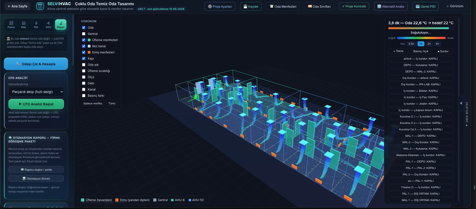
It solves multi-room HVAC design for pharmaceutical and GMP cleanroom facilities in a single flow: thermal loads, air changes, the pressure cascade, the door leakage network, AHU psychrometrics and the desiccant branch are all produced under one calculation identity — from the inputs through to a signed handover package.
Cleanroom Calculation Software is an engineering engine that solves multi-room HVAC design end to end for pharmaceutical and GMP cleanroom facilities. Thermal loads, air change rates, the pressure cascade, the door leakage network, air handling unit psychrometrics and the steam-regenerated desiccant branch are not solved in disconnected spreadsheets but together, under a single calculation identity. So when a room's classification, volume or pressure changes, the adjacent door flows, the cascade direction and the unit load all update automatically and consistently.
The engine is built on physics, not shortcuts. Every door between rooms is modelled as an orifice; the air leaking through the door gap is calculated from the opening area and the pressure difference between the two rooms. The pressure cascade, the particle recovery time and the zero-pressure path of the external door to atmosphere are all held within the same network. Air change and classification targets follow ISO 14644 and EU GMP Annex 1; air handling unit psychrometrics follow ASHRAE Fundamentals. Donor (make-up) air is solved with full circuit conservation — the mass balance is never forced with synthetic corrections. Where an existing unit is present, a RERATE comparison is made against site data for capacity, operating regime and climate, and missing data is marked explicitly as "not verified". Every one of these calculations is carried out with each assumption that affects the result shown openly.
Every document produced carries the same frozen calculation snapshot and its SHA-256 identity: the CAS Excel workbook (calculation sheets, equipment list, pressure cascade, general P&ID, standards), the PDF calculation and psychrometric report, site approval and test forms, the automation Excel package and the pipework P&ID. The software never gives "clearance to order" without a manufacturer selection and site evidence — gaps and model limits are reported explicitly on the output. That keeps the design traceable and defensible from tender through to commissioning.
Draw the rooms, assign classification and air changes, and assess the supply and extract pattern against real-time particle flow.
From a real project: 20 rooms, 21 active door connections. The cleaner room is always at the higher pressure — the pressure difference and flow direction are verified at every door, with GMP breach checking.
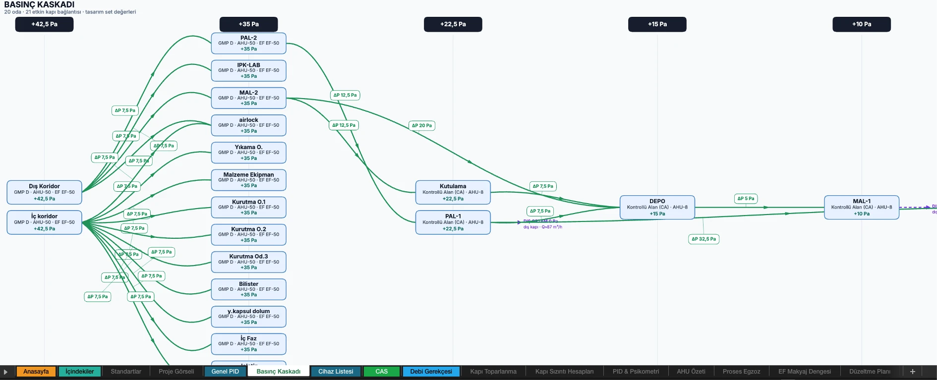
How it is solved: every door is modelled as an orifice, and the leakage flow follows from the opening area and the pressure difference between the two rooms. The cascade, the recovery time and the external door's zero-pressure path are held in one network — change one room's pressure and the adjacent pressure differences and the unit flow update at the same time. Direction is checked so the cleaner room is always at the higher pressure, and a warning is raised on any breach.
Classification, temperature and humidity, filter stages, dimensions, load and air changes for every room, with totals by air handling unit.
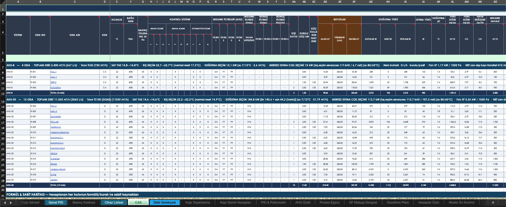
It works with every assumption that affects the result shown openly. The quantities the software solves, in plain language:
Finds how much air each door will leak, from the door gap and the pressure difference between the two rooms, and solves the pressure tiers of all rooms as one network.
Calculates how many times an hour the supply air renews the room volume, and meets the target for the cleanliness classification.
Finds the cooling and heating capacity needed to bring the air to the required temperature and humidity, separating the heat load from the moisture load.
Solves mixing, cooling, heating and reheat steps, and the dehumidification (desiccant) and humidification demand, separately for summer and winter.
Finds the water quantity the cooling and heating coils require, for the chosen temperature regime.
Calculates the power the fan will draw to overcome the filter stages and duct resistances, including the dirty filter condition.
Assesses how far the recovery device pre-conditions the fresh air, and shows the energy gained.
Estimates how long the air takes to return to its target cleanliness after a contamination event (the GMP Annex 1 recovery test).
Balances supply, extract and leakage; distributes donor, make-up and transfer air consistently and directs the net leakage to the external door.
Lay the rooms out on plan; dimensions, volumes and door adjacencies follow automatically.
Assign the ISO 14644 / GMP target; thermal load and fresh air are calculated.
Coils, reheat, heat recovery and the desiccant branch are solved.
The door leakage network and pressure directions are verified with GMP breach checking.
Dead zones and short circuiting are assessed in 3D through particle flow.
CAS Excel, P&ID and reports are produced under one identity — ready to sign.
Everything the software covers, from the calculation engine to the handover package, under four headings.
Get in touch for access and licensing, or request a demo.