A foam system has three lines: water, concentrate and the foam solution where they mix. A sound installation depends on concentrate joining the water at the right rate and flow, on each line being built from the right material, and on a shutdown sequence marked so it cannot be done wrong.
This article puts the equipment, the P&ID, the fixed-roof tank calculation and the site installation sequence in one place. For design steps see the foam system design guide, and for supply rules see the concentrate and proportioning article.
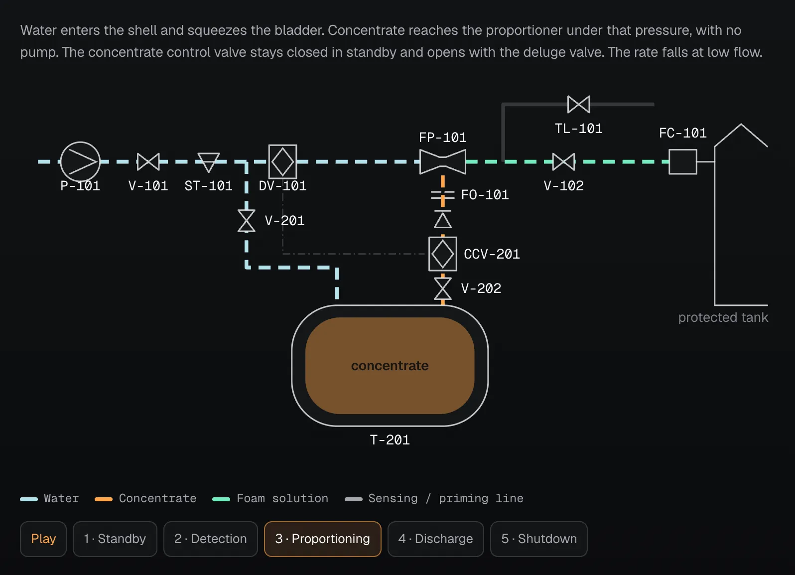
How the system works: animated P&ID
All four methods share the same upper line: water source, main valve, strainer, deluge valve, proportioner, solution line and discharge outlet. They differ in how concentrate reaches the proportioner.
Which proportioning method?
NFPA 11 treats balanced-pressure or positive-pressure injection as the preferred methods for fixed systems (4.5.2.1). The choice depends on the concentrate type, the flow range and whether power is available for a pump.
| Method | Energy | Behavior at low flow | Watch for | Clause |
|---|---|---|---|---|
| Bladder pressure tank | Pressurized water | Rate drops markedly; not used below its design range | Tank water feed is taken after the main valve, before the deluge valve | 4.5.2.2(2), A.4.5.2.2, 10.5.7.2 |
| Balanced-pressure pump | Concentrate pump | Rate rises above the anticipated value | Diaphragm balancing valve and sensing lines | 4.5.2.2(1), A.4.5.2.2 |
| In-line balanced pressure | Pump or bladder tank | Supply pressure held constant at all flows | Concentrate pressure must stay above water pressure; at least 1 bar on Viking | 4.5.2.2(3), Viking F_031516 |
| In-line eductor | Water flow | Depends on the listed limits | Recommended only for open-head or deluge systems | 4.5.2.3(3), A.4.5.2.3(3) |
Whichever method you use, the proportioner must not run below its listed minimum flow (4.5.1). Some alcohol-resistant foam proportioners need much higher flows to reach that limit (A.4.5.1). The concentrate must also be listed with the proportioner and discharge device (4.1.2).
Equipment list
| Equipment | Key rule | Clause |
|---|---|---|
| Concentrate (atmospheric) tank | Compatible material, room for thermal expansion, suction inlet at least 25 mm above the bottom, sediment pocket volume added | 4.3.2.3.1.4, 4.3.2.3.2 |
| Pressure bladder tank | Means for filling, level gauging, draining and bladder inspection; ASME Section VIII stamp | 4.3.2.3.3 |
| Concentrate pump | Listed for this service, starts automatically, has flushing means and a drain valve; discharge pressure above the highest water pressure | 4.6.2.2, 4.6.4–4.6.6 |
| Pressure relief valve | Relieves from pump discharge to suction; pressure stays within the working pressure of the concentrate piping | 4.6.3, 10.1 |
| Proportioner and orifice | Orifice plate permanently marked with the diameter and, if relevant, flow direction | 4.5.1, 4.5.2.4 |
| Strainer | Open basket area at least 10 times the inlet pipe area, net open area at least 4 times the suction pipe area. On the concentrate line, only if the proportioning system manufacturer accepts it | 4.7.5, note to Figure A.4.5.2.2 |
| Valves | Indicator type on water and solution lines (such as OS&Y); supervised open on automatic systems; fire-resistant material inside a dike or hazard | 4.7.6 |
| Detection and control | Supervised automatic detection; local alarm and alarm at a constantly attended location; manual actuation on every system | 4.9.1, 4.9.2 |
| Discharge outlet | Attached at the top of the tank shell, with a vapor seal and access to inspect it | 5.2.5.1 |
Orifice flow is Qf = K·C·d²·√ΔP. K is specific to the concentrate and comes from the manufacturer; C is affected by orifice shape, viscosity, velocity and diameter ratio (A.4.5.2.2). So the orifice diameter is not chosen without manufacturer data.
Calculation: fixed-roof tank
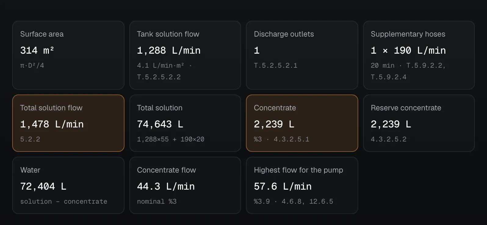
The calculation is built on the tank needing the largest solution flow, plus the supplementary hose streams (5.2.2). Change the tank diameter and watch the outlet and hose counts change at the table limits.
Worked example
A 20 m fixed-roof tank, flash point below 38 °C, Type II outlet, 3% concentrate:
| Step | Working | Result | Clause |
|---|---|---|---|
| Surface area | π × 20² / 4 | 314 m² | |
| Tank solution flow | 314 × 4.1 L/min·m² | 1,288 L/min | T.5.2.5.2.2 |
| Discharge outlets | Up to 24 m | 1 | T.5.2.5.2.1 |
| Supplementary hose | Up to 20 m: 1 hose at 190 L/min; 11–29 m: 20 min | 190 L/min | T.5.9.2.2, 5.9.2.3, T.5.9.2.4 |
| Total solution flow | 1,288 + 190 | 1,478 L/min | 5.2.2 |
| Total solution | 1,288 × 55 + 190 × 20 | 74,643 L | |
| Concentrate | 74,643 × 3% | 2,239 L | 4.3.2.5.1 |
| Water | 74,643 − 2,239 | 72,404 L | |
| Reserve | As much as the worst case; separate tank, drums or an approved outside source within 24 h | 2,239 L | 4.3.2.5.2 |
| Highest flow for the pump | 1,478 × 3.9% | 57.6 L/min | 4.6.8, 12.6.5 |
The last row is often skipped. The acceptance tolerance lets the rate rise to 3.9% (+30 percent, or +0.9 points, is less than +1 point), and the concentrate pump must meet that highest proportioning flow. With 6% concentrate the limit is 7%, at +1 point.
Three cautions. The tank with the largest flow is not always the one needing the most concentrate (A.4.3.2.2), so calculate every tank. With higher-rate equipment the time may be reduced proportionately, but not below 70 percent of the table time (5.2.5.2.3). For liquids needing alcohol-resistant foam the rate comes from the manufacturer's listing, and this calculation does not apply (5.2.5.3.4). For floating roofs, dikes, loading racks and spills use the foam concentrate calculator.
What the Viking and Tyco documents add
NFPA 11 says what the system must do; the manufacturer's document supplies sizes and piping arrangement. The values below apply to that manufacturer's own product and do not carry over to others.
Viking: deluge foam system with bladder tank
Viking's technical bulletin (F_102921 Rev 01, March 2024) defines the system as a deluge valve, a proportioner, a concentrate control valve (CCV) and a bladder tank.
- Tank water feed: Recommended below the deluge valve to avoid water hammer. This fits NFPA 11's "above the control valve" rule (10.5.7.2): the feed sits between the main valve and the deluge valve.
- CCV: Primed from the deluge valve line and closed in standby. It is closed when its gauge reads system pressure. Viking recommends a CCV for all foam systems, and FM projects require one under DS 4-12 (pre-pipe package document, Rev 24.1).
- Pipe length: Combined equivalent length of the tank water feed and concentrate line should not exceed 50.3 m: 30.5 m water and 19.8 m concentrate. The CCV and check valve connect right beside the proportioner with short nipples.
- Straight pipe: At least 5 pipe diameters before and after the proportioner. A foam test valve closer than this may cause turbulence at high flow.
- Strainer: Not required on a bladder tank concentrate line.
- Commissioning: Open the tank water valve and concentrate shutoff valve slowly, vent the tank and check for leaks.
- After a test: Flush the concentrate line downstream of the CCV by feeding water at the commissioning valve and through the test header.
- Proportioner limits (F_102421 Rev 02, 2023): Design pressure 17.2 bar, inlet pressure 2.1–12.1 bar. Flow ranges can differ between FM and UL, so use the table for your listing and check pressure loss on the curve.
- Over-discharge (F_101798 Rev 03, 2025): If a deluge system discharges more than calculated, concentrate may run out before the required time. Calculate the supply at the actual discharge flow.
Tyco: bladder tank and in-line proportioner
- Bladder tank (F-83179-12, 2013; CG-2015130, 2016): A flexible bladder inside a steel pressure vessel. No energy other than pressurized water is needed. Vertical 189–5,678 L, horizontal 379–11,356 L. Maximum working pressure 12.1 bar; compare it with the highest system pressure. Water inlet and concentrate outlet are 2½ in up to 3,785 L and 3 in above that. A label on the tank states the concentrate type and quantity.
- In-line proportioner (CG-2015145-01, 2016): Works with an atmospheric tank and a positive displacement pump. A pressure control valve in the return line holds supply pressure above water pressure, a spool valve balances the two and a duplex gauge shows both.
- Nominal flow range: 2 in 114–1,136 L/min, 3 in 265–3,028 L/min, 4 in 757–6,057 L/min, 6 in 1,136–12,870 L/min, 8 in 1,892–20,819 L/min. These ranges do not apply to alcohol-resistant concentrate. The rate rises slightly at the low end.
The rule for sizing the tank stays the same: the calculated concentrate must fit within the usable volume the manufacturer lists. Filling and maintenance follow the manual supplied with the tank.
Pipe, fitting and valve materials
The most expensive site mistake sits in this table: pipe used on the water line cannot go on the concentrate line.
| Concentrate line | Foam solution line | |
|---|---|---|
| Line limits | Tank to the proportioner's side inlet (A.4.7.1) | Proportioner outlet to the discharge device (A.4.7.2) |
| Suitable material | Brass, bronze, stainless 304/316, copper-nickel 90/10 (4.7.1.1) | Galvanized steel, stainless 304/316, copper-nickel 90/10 (4.7.2.1) |
| Banned or limited | No carbon steel or galvanized pipe (4.7.1.2, 4.7.1.3) | Unprotected carbon steel only when filled and with discharge devices closed to the atmosphere (4.7.2.1(5)) |
| Wall thickness | Schedule 40 or ASME B31.1 (4.7.1.6) | Metallic pipe at least standard weight (4.7.2.6) |
| Friction loss | Darcy-Weisbach for Newtonian concentrate; manufacturer data for alcohol-resistant concentrate (4.7.1.7) | Hazen-Williams; C = 120 for galvanized steel (4.7.2.9) |
| Pitch (dry line) | At least 4 mm/m (4.7.1.9) | At least 4 mm/m (4.7.2.10) |
| Joints | PTFE tape or thread compound the concentrate manufacturer accepts (4.7.4.1.2) | Precautions against galvanic corrosion between metals (4.7.4.3.4) |
Some fluoroprotein concentrates are incompatible with stainless steel (A.4.7.1.1). Confirm the material with the concentrate manufacturer.
Installation sequence
- Plans and approval. Plans are prepared by experienced people, to scale or dimensioned (9.3.1, 9.3.2). Hydraulic calculations and pump curves are supplied (9.3.6, 9.3.7).
- Concentrate room. Tank and equipment go where the hazard will not expose them, in a noncombustible structure if housed (4.3.2.1). The tank is solidly and permanently mounted (4.3.2.3.1.1). Listed temperature limits are kept (4.3.2.4.2).
- Water line and proportioner. Each proportioner's water inlet is separately valved (10.5.3). Parallel proportioners have a valve between each outlet and the header (10.5.2). On a single riser, the bladder tank water feed is taken above the control valve (10.5.7.2). Place the tank near the riser with room around it for maintenance (Viking F_102921).
- Pump and power. Power is arranged so disconnecting the facility does not disconnect the pump feeder (10.3.2). The controller is limited service up to 30 hp electric, full service fire pump above that, and a diesel engine controller on diesel (10.3.3).
- Tank field piping. Pipe inside dikes or within 15 m of undiked tanks is buried under at least 300 mm of earth, or supported above ground and protected from mechanical damage (10.4.1). Each riser has a flange or union for hydrostatic testing (10.4.3).
- Outlet valves. Outlets are individually piped and separately valved outside the dike (5.2.5.1.2.1, 10.5.1). The valves are at least one tank diameter from the tank and never less than 15 m (10.5.1.3).
- Hangers and routing. Where explosion is possible, pipe takes the best-protected route (10.6.1). Pipe feeding one hazard does not pass over another hazard in the same fire area (10.6.2).
- Test and drain points. Fit valves and hose connections for proportioning tests, a 15 mm gauge connection at the most remote outlet and accessible drain valves at low points (10.8, 10.8.1, 10.5.6).
- Signs. Mark the tank with the concentrate type and percentage (4.3.2.4.3). Post the correct shutdown sequence (4.3.2.3.1.3).
Acceptance tests
| Test | Criterion | Clause |
|---|---|---|
| Visual examination | Conformity with plans, pipe continuity, temporary blinds removed, access to valves, vapor seals | 12.1 |
| Flushing | Supply mains at no less than the system demand rate; system piping with its normal water supply and foam materials shut off | 12.2 |
| Pressure test | 2-hour hydrostatic: 1,379 kPa or 345 kPa above the maximum pressure, whichever is greater | 12.4.1 |
| Operating test | All devices, electrical control and supervisory circuits; control valves fully closed and opened under water pressure | 12.5 |
| Discharge test | Record static and residual pressure, actual flow, concentrate consumption and concentration | 12.6.3 |
| Concentration | Digital refractometer, digital conductivity meter or listed flow meters; result within −0 to +30 percent or +1 point | 12.6.2, 12.6.5 |
| Restoration | System flushed and returned to service; contractor signs the test certificate | 12.7, 12.8 |
The proportioning system may also be tested by a listed or approved method that does not discharge concentrate (12.6.4). For periodic maintenance see the acceptance test and maintenance article.
Common mistakes
- Galvanized concentrate line: Explicitly banned (4.7.1.3).
- Bladder tank at low flow: The rate falls and the foam is weak. Check the method at the smallest hazard's flow too (4.5.1, A.4.5.2.2).
- Memorizing a shutdown order regardless of the system: With the feed below the main valve, or on a pump system, cutting water first sends concentrate into the depressurized line (A.4.3.2.3.1.3). On Viking's arrangement with the feed after the main valve, an emergency shutdown starts at the main water valve (F_102921). Follow the posted sequence.
- Mixing concentrates: Different types are not mixed in storage. Different brands of one type mix only with manufacturer data accepted by the AHJ (4.4.1). Viking says never to intermix them (F_102921).
- Forgetting the reserve: Supply to return the system to service after a fire is also required (4.3.2.5.2.1).
Frequently Asked Questions
How do you choose a foam proportioning method?
NFPA 11 prefers balanced-pressure or positive-pressure injection for fixed systems (4.5.2.1). Without a pump a bladder pressure tank can be used, but its rate falls at low flow. The method must suit the system's minimum and maximum flow (4.5.1).
Can galvanized pipe be used on a foam concentrate line?
No. NFPA 11-2024 bans carbon steel and galvanized pipe on the concentrate line (4.7.1.2, 4.7.1.3). Use brass, bronze, stainless 304/316 or copper-nickel 90/10.
How much concentrate does a 20 m fixed-roof tank need?
With a flash point below 38 °C, a Type II outlet and 3% concentrate: 1,288 L/min × 55 min for the tank and 190 L/min × 20 min for the hose. That is 74,643 L of solution and 2,239 L of concentrate. The same reserve is also required (4.3.2.5.2).
Which valve closes first when shutting down a foam system?
It depends on the arrangement. With the water feed below the main valve, or on a pump system, close the concentrate valve first or concentrate escapes into the depressurized line (A.4.3.2.3.1.3). On Viking's bladder tank arrangement with the feed after the main valve, an emergency shutdown starts at the main water valve (F_102921). The posted sequence governs (4.3.2.3.1.3).
What is the proportioning tolerance?
−0 to +30 percent of the listed concentration, or +1 percentage point, whichever is less (12.6.5). That gives an upper limit of 3.9% for 3% concentrate and 7% for 6% concentrate.
How is a foam system hydrostatically tested?
The piping gets a 2-hour hydrostatic test at 1,379 kPa or 345 kPa above the maximum anticipated pressure, whichever is greater (12.4.1). Lines handling expanded foam are excluded, except for subsurface application.

SprinkCalc — Fire Sprinkler Design Across Three Standards
SprinkCalc covers hazard classification, design density and area, K-factor selection, water demand and hydraulic calculations for NFPA 13, FM Global and BS EN 12845 in a single iOS app, and exports a professional PDF report.
Download SprinkCalc on the App Store
MEP Calc — 110+ Engineering Calculators
MEP Calc bundles 110+ engineering modules in one iOS app: 21 fire calculations plus heating, cooling, HVAC, plumbing, steam and natural gas.
Download MEP Calc on the App StoreNFPA 11-2024 (Chapters 4, 5, 9, 10, 12; Annex A). Viking technical documents: F_102921 Rev 01 (2024), F_101798 Rev 03 (2025), F_102421 Rev 02 (2023), F_031516 Rev 05 (2025), pre-pipe package TD1.3.1.2 Rev 24.1. Tyco Fire Products data sheets: F-83179-12 (2013), CG-2015130 (2016), CG-2015145-01 (2016). Diagrams were drawn for this article.