One of the most common questions in a fire pump room is: where does the relief valve go, and what happens if it is installed in the wrong place? NFPA 20-2025 calls this valve the “main relief valve” and restricts it to a narrow set of cases in Section 4.20. This article sets out the rule clause by clause and the reasoning from the standard’s Annex A and the NFPA 20 Handbook (2022) commentary. The Handbook calls the same valve a “pressure relief valve”.
In short: a main relief valve is used only where the standard specifically permits it (4.20.1.1). On a constant-speed diesel pump it is required when 121 percent of the net rated churn pressure plus the maximum static suction pressure exceeds the pressure rating of the system components (4.20.1.2). It is located between the pump and the pump discharge check valve (4.20.3.1), with no shutoff valve in its supply or discharge piping (4.20.9). It may not be used to reduce pressure in normal operation (4.7.7.2).
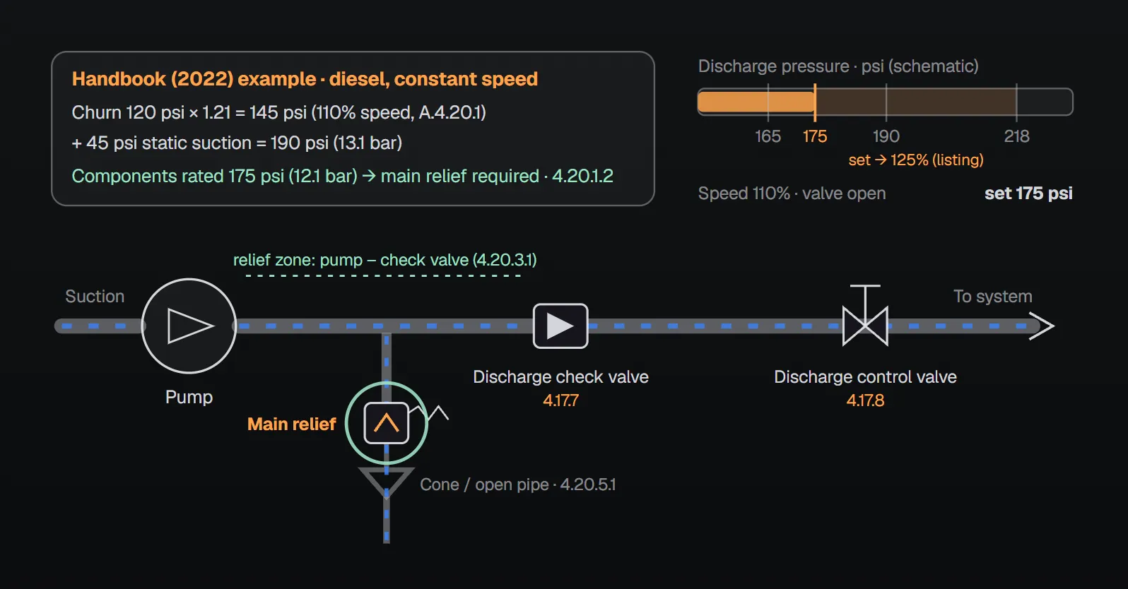
When is a main relief valve required?
The standard defines the main relief valve as one that automatically relieves excessive pressure caused by an overspeed condition in the driver or engine by discharging water to the environment or back to suction (3.3.78.4.2). The conditions are narrow:
- Diesel engine pump: install the valve where 121 percent of the net rated shutoff (churn) pressure plus the maximum static suction pressure, adjusted for elevation, exceeds the pressure rating of the system components (4.20.1.2).
- Electric variable speed pump or diesel pressure-limiting driver: install the valve where the maximum total discharge head, adjusted for elevation, at shutoff and rated speed exceeds the pressure rating (4.20.1.3). It is set at least 10 psi (0.68 bar) above the set pressure of the variable speed pressure-limiting control (4.20.1.3.1).
- Not a pressure-reducing device for normal operation: net churn pressure plus maximum static suction pressure must not exceed the component rating (4.7.7.1), and relief valves or pressure-regulating devices may not be used to meet this (4.7.7.2). Annex A.4.7.7 states a relief valve is not an acceptable method of reducing system pressure under normal operating conditions.
Where does 121 percent come from?
Per Annex A.4.20.1, pump pressure is proportional to the square of speed; a diesel governor must be able to limit maximum engine speed to 110 percent, which creates 121 percent pressure. Because the main relief valve is needed only when the engine runs faster than normal, a relatively rare event, its discharge may be piped back to pump suction (A.4.20.1).
| Handbook (2022) calculation example | Value |
|---|---|
| Pump rating | 1500 gpm (5677 L/min), 100 psi (6.9 bar), 1750 rpm |
| Shutoff (churn) pressure | 120 psi (8.3 bar) |
| Shutoff pressure at 110% speed | 120 × 1.21 = 145 psi (10 bar) |
| Maximum static pressure from city supply | 45 psi (3.1 bar) |
| Total | 145 + 45 = 190 psi (13.1 bar) |
| Components rated 175 psi (12.1 bar) | Main relief valve required |
| Components rated 200 psi (13.8 bar) or higher | Not required |
The Handbook adds that using a main relief valve to trim excess pressure is considered poor design, and lists alternatives such as a break tank, a variable speed pressure-limiting control, or pressure-regulating devices downstream of the pump discharge control valve. Annex A.4.20.1.1 likewise notes that a tank or a variable speed pressure-limiting control might be needed where the required system pressure is close to the component rating and supply pressure varies significantly over time.
Where is it installed?
- Between the pump and the pump discharge check valve (4.20.3.1).
- Attached so it can be readily removed for repairs without disturbing the piping (4.20.3.2).
- With no shutoff valve in its supply or discharge piping (4.20.9).
Why there? The NFPA 20 Handbook (2022) explains that when the valve operates, water is discharged as it leaves the pump but before it reaches fire protection system piping, limiting system pressure downstream of the valve. What if it is installed elsewhere? Neither the standard nor the Handbook describes the outcome of placing it on the system side of the check valve; 4.20.3.1 simply states the location. The standard also gives no reason for the shutoff valve prohibition (4.20.9). The “wrong place” errors for which the sources do give a reason are on the discharge side and are collected in the table below.
Type, size and setting
- Listed spring-loaded or pilot-operated diaphragm type (4.20.4.1). On vertical shaft turbine pumps, a pilot-operated valve is arranged so it does not relieve water below its setting (4.20.4.2).
- The size may be determined hydraulically (4.20.2.1; sample calculation in Figure A.4.20.2.1); otherwise it may not be smaller than the value in Section 4.28 (4.20.2.2).
- NFPA 20 Handbook (2022) commentary: the listing standard requires listed relief valves to limit upstream pressure to 125 percent of the setting, so a valve set at 175 psi (12.1 bar) could allow 218 psi (15 bar) and still pass. Spring-operated valves do not fully open until the set pressure is exceeded; pilot-operated valves should hold the maximum closer to the setting. Review the operating characteristics before selecting a valve.
Discharge: where does the water go?
- The valve discharges into an open pipe or into a cone or funnel secured to its outlet (4.20.5.1). Discharge must be readily visible or easily detectable by the pump operator (4.20.5.2) and splashing into the pump room avoided (4.20.5.3). A closed cone needs a means of detecting water motion through it (4.20.5.4); if the valve itself detects flow, no cone is required (4.20.5.5).
- The discharge pipe is at least the Section 4.28 size (4.20.6.1); with more than one elbow, use the next larger size (4.20.6.1.1). Hydraulic sizing is also permitted (4.20.6.2).
- Piping returning to the supply source, such as an aboveground tank, runs independently and is not combined with other relief valve discharges (4.20.6.3). A single pump’s line may join test piping downstream of any control valve (4.20.6.4); lines from multiple main relief valves may not (4.20.6.5); the test header piping must be isolatable (4.20.6.6). Capacity must keep pressure below the component rating (4.20.7); Annex A.4.20.7 notes that back pressure may require a larger valve and pipe.
- When piped back to suction, a circulation relief valve discharging to atmosphere is added downstream of the main relief valve (4.20.7.1) and actuates below the main relief opening set point (4.20.7.2). With a heat-exchanger-cooled diesel, the controller gives a visual and audible alarm on high cooling water temperature and stops the engine if there is no active emergency demand (4.20.7.3); this does not apply when water returns to a storage reservoir (4.20.7.3.1).
Common field errors and the reason given in the sources
| Error | Rule | Reason in the sources |
|---|---|---|
| Using the valve to trim normal operating pressure | 4.7.7.2 | A.4.7.7: not an acceptable method; Handbook: poor design |
| Placing the valve on the system side of the check valve | 4.20.3.1 | Handbook: discharge happens before water reaches system piping; outcome not described |
| Shutoff valve in the relief piping | 4.20.9 | No reason given in the standard |
| Combining relief lines returning to the source | 4.20.6.3 | Handbook: back pressure on other valves; one pump cannot be isolated to repair its valve |
| Connecting circulation relief or flowmeter discharge to the relief drain | 4.20.6.3 commentary | Handbook: should not be connected, for the same reasons |
| Omitting the extra circulation relief valve when returning to suction | 4.20.7.1 | Handbook: the Section 4.13 valve might close while the relief valve flows; the extra valve cools the pump |
| Discharging near the suction of a limited reservoir | 4.20.8 | The pump could draft air introduced by the discharge; A.4.20.8: entry below minimum water level |
| Connecting the cone to an underground drain near steam drains | A.4.20.5 | Steam could work back through the cone into the pump room; preferably discharge outside |
Checklist
- Has the 4.20.1.2 or 4.20.1.3 check been done; is the valve actually required?
- Is the valve between the pump and the discharge check valve, and removable (4.20.3)?
- No shutoff valve in the supply or discharge piping (4.20.9)?
- Listed spring-loaded or pilot diaphragm type, with the 125 percent behaviour considered (4.20.4.1)?
- Discharge visible, no splashing, flow detection on a closed cone (4.20.5)?
- When returning to suction: extra circulation relief valve and diesel cooling alarm (4.20.7.1–4.20.7.3)?
Frequently Asked Questions
Where is the main relief valve installed on a fire pump?
Between the pump and the pump discharge check valve, attached so it can be removed for repair without disturbing the piping (NFPA 20-2025 4.20.3.1, 4.20.3.2). No shutoff valve is permitted in its supply or discharge piping (4.20.9).
What happens if the relief valve is installed in the wrong place?
The NFPA 20 Handbook (2022) explains that the valve discharges water as it leaves the pump, before it reaches system piping, limiting downstream pressure. Neither the standard nor the Handbook describes the outcome of placing it on the system side of the check valve; 4.20.3.1 simply states the location. Reasons are given for discharge-side errors, for example discharging near the suction of a limited reservoir can let the pump draft air (4.20.8).
Does every diesel fire pump need a main relief valve?
No. It is required where 121 percent of net churn pressure plus maximum static suction pressure exceeds the component rating (4.20.1.2). In the Handbook (2022) example, 120 psi churn × 1.21 = 145 psi plus 45 psi = 190 psi (13.1 bar): required with 175 psi components, not with 200 psi or higher.
Can the main relief valve be used to reduce system pressure?
No. Churn plus maximum static suction pressure must not exceed the component rating, and relief valves or pressure-regulating devices may not be used to achieve this (4.7.7.1, 4.7.7.2). Annex A.4.7.7 says it is not an acceptable method under normal operating conditions.
Can main relief valve discharge be piped back to pump suction?
Yes (A.4.20.1). A circulation relief valve discharging to atmosphere is then added downstream of the main relief valve and set below its opening point (4.20.7.1, 4.20.7.2); a heat-exchanger-cooled diesel needs a high cooling water temperature alarm and shutdown (4.20.7.3).

SprinkCalc — Fire Sprinkler Design Across Three Standards
SprinkCalc covers hazard classification, design density and area, K-factor selection, water demand and hydraulic calculations for NFPA 13, FM Global and BS EN 12845 in a single iOS app, and exports a professional PDF report.
Download SprinkCalc on the App Store
MEP Calc — 110+ Engineering Calculators
MEP Calc bundles 110+ engineering modules in one iOS app: 21 fire calculations plus heating, cooling, HVAC, plumbing, steam and natural gas.
Download MEP Calc on the App StoreNFPA 20-2025, Standard for the Installation of Stationary Pumps for Fire Protection: 3.3.78.4, 3.3.78.4.2; 4.7.7.1, 4.7.7.2; 4.20.1–4.20.9; Annex A.4.7.7, A.4.20.1, A.4.20.1.1, A.4.20.2.1, A.4.20.5, A.4.20.7, A.4.20.8 (explanatory). NFPA 20 Handbook 2022 commentary: Section 4.20 (4.20.1.2 calculation example, 4.20.4.1 listing note, 4.20.5 and 4.20.6.3 commentary, 4.20.7.1 commentary) and the “Controlling Excess Fire Pump Pressures” feature.