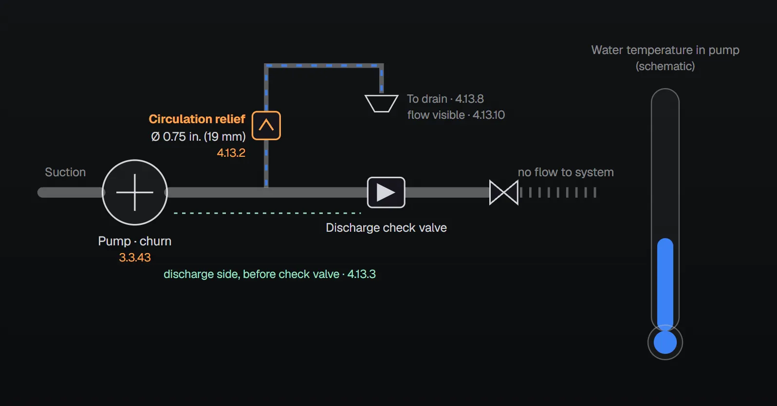
A fire pump can run while delivering no water to the system; this is the shutoff (churn) condition. NFPA 20-2025 defines it as the condition where the only water passing through the pump is a small flow discharged through the circulation relief valve or supplying diesel engine cooling (3.3.43). This article covers why the circulation relief valve is needed, its size, location and setting, using Section 4.13.
In short: every fire pump gets an automatic circulation relief valve listed for fire pump service (4.13.1). It is 0.75 in. (19 mm) nominal for pumps rated 2500 gpm (9462 L/min) or less and 1 in. (25 mm) for 3000 to 5000 gpm (11,355 to 18,925 L/min) (4.13.2). It goes on the discharge side before the discharge check valve (4.13.3) and is set below the shutoff pressure at minimum expected suction pressure (4.13.5).
Why is it needed?
The standard defines the circulation relief valve as a valve, separate from and independent of the main relief valve, used to cool a pump by discharging a small quantity of water (3.3.78.4.1). It must provide enough flow to prevent the pump from overheating when operating with no discharge (4.13.7).
The NFPA 20 Handbook (2022) commentary states the reason plainly: at churn, energy is continuously imparted to the water in the impeller and the water heats. For electric pumps and radiator-cooled engine pumps, this valve provides the cooling water. Failure or omission of the valve can result in overheating and damage to the pump.
Rule table
| Topic | Rule | Clause |
|---|---|---|
| Requirement | An automatic valve listed for fire pump service on each fire pump | 4.13.1 |
| Exception 1 | Vertical lineshaft turbine taking water from a non-pressurized tank or can | 4.13.1.1 |
| Exception 2 | Engine-driven pump taking engine cooling water from the pump discharge | 4.13.1.2 |
| Size | ≤ 2500 gpm (9462 L/min): 0.75 in. (19 mm); 3000–5000 gpm (11,355–18,925 L/min): 1 in. (25 mm) | 4.13.2 |
| Location | Discharge side, before the discharge check valve | 4.13.3 |
| Multistage multiport pump | Before the check valve for the last port; set below the churn pressure of the first port | 4.13.4 |
| Setting | Below the shutoff pressure at minimum expected suction pressure | 4.13.5 |
| Discharge | Provision to discharge to a drain; not tied in with packing box or drip rim drains; drain flow visible | 4.13.8–4.13.10 |
| Supply | One of the fittings provided where necessary by the pump manufacturer or authorized representative | 6.3.1(2) |
Because the ratings in Table 4.10.2 jump from 2500 gpm straight to 3000 gpm, the two sizes in 4.13.2 cover every standard rating; pumps over 5000 gpm (18,925 L/min) are subject to individual review by the authority having jurisdiction or a listing laboratory (4.10.3).
Location: why before the check valve?
Per the Handbook (2022) commentary, the connection must be on the discharge side of the pump so that flow passes through the pump casing, and should discharge outdoors or to a floor drain where the pump operator can see it. On a multiport pump, placing the valve after the last port provides flow through each impeller; the Handbook notes that even when one port is flowing, a cooling flow is still needed for the ports downstream of it (4.13.4 commentary).
The Handbook also recommends installing the valve in the vertical position, because in a horizontal position debris collecting in the valve seat might cause accelerated failure. This is Handbook advice, not a requirement of the standard.
Electric variable speed pumps
- An additional circulation relief valve or a temperature-actuated relief valve may be used (4.13.6).
- The additional automatic valve is set to open at the minimum operating speed (4.13.6.1). Annex A.4.13.6.1: under no-flow conditions the jockey pump might keep system pressure above the set pressure, causing the variable speed control to slow down; a small amount of water still has to be discharged to cool the pump.
- A restricting orifice limits the flow to what is needed to keep the pump cool at minimum speed (4.13.6.2). Annex A.4.13.6.2: because this setting is much lower than for bypass operation, flow to the drain in bypass mode would be large enough to overwhelm the drain; the 4.13.1 valve is set as on a constant-speed pump.
When the main relief valve returns to suction
If the main relief valve discharge is piped back to pump suction, a second circulation relief valve, sized per 4.13.2 and 4.20.7 and discharging to atmosphere, is installed downstream of the main relief valve (4.20.7.1); it actuates below the main relief valve’s opening set point (4.20.7.2). The Handbook (2022) explains that the Section 4.13 valve is designed for churn and might close while water flows through the main relief valve; the second valve cools the pump during that time. Its setting should be well below the main relief setting but above the maximum suction pressure.
With a heat-exchanger-cooled diesel, the controller gives a visual and audible alarm on a high cooling water temperature signal and stops the engine if there is no active emergency demand (4.20.7.3); this does not apply when the water returns to a storage reservoir (4.20.7.3.1).
Common field errors
- Shutting the valve during the test: Annex A.14.2.6.1 says the small discharge through the circulation relief valve should not be shut off during the test because it keeps the pump from overheating; the minimum-flow test condition is no flow to the system with a small flow through this valve.
- Tying into packing box or drip rim drains: prohibited by 4.13.9; the standard gives no reason.
- Hidden drain: drain flow must be visible (4.13.10).
- Connecting to the main relief drain: the Handbook says discharge from devices such as the circulation relief valve should not be connected to the main relief drain piping (4.20.6.3 commentary).
- No orifice on the extra valve of a variable speed pump: per A.4.13.6.2 the drain can be overwhelmed in bypass mode.
Checklist
- Is the valve listed and automatic; does an exception (4.13.1.1, 4.13.1.2) really apply?
- Is the size right for the pump rating (4.13.2)?
- Discharge side, before the check valve (4.13.3)?
- Set below the shutoff pressure at minimum expected suction pressure (4.13.5)?
- Separate drain with visible flow (4.13.8–4.13.10)?
- Extra valve and orifice for variable speed; second valve when the main relief returns to suction (4.13.6, 4.20.7.1)?
Frequently Asked Questions
What does a circulation relief valve do?
It cools the pump by discharging a small quantity of water while the pump runs with no flow to the system (churn) (NFPA 20-2025 3.3.78.4.1, 4.13.7). The NFPA 20 Handbook (2022) notes that water heats at churn and that failure or omission of the valve can result in overheating and pump damage.
What size is the circulation relief valve?
0.75 in. (19 mm) nominal for pumps rated 2500 gpm (9462 L/min) or less and 1 in. (25 mm) for pumps rated 3000 to 5000 gpm (11,355 to 18,925 L/min) (4.13.2).
Where is the circulation relief valve installed?
On the discharge side of the pump before the discharge check valve (4.13.3). On multistage multiport pumps it goes before the check valve for the last port and is set below the churn pressure of the first port (4.13.4).
Which pumps do not need a circulation relief valve?
A vertical lineshaft turbine taking water from a non-pressurized tank or can (4.13.1.1) and an engine-driven pump whose engine cooling water is taken from the pump discharge (4.13.1.2).
May the circulation relief valve be shut during a pump test?
No. Annex A.14.2.6.1 says this small discharge should not be shut off during the test because it keeps the pump from overheating.

SprinkCalc — Fire Sprinkler Design Across Three Standards
SprinkCalc covers hazard classification, design density and area, K-factor selection, water demand and hydraulic calculations for NFPA 13, FM Global and BS EN 12845 in a single iOS app, and exports a professional PDF report.
Download SprinkCalc on the App Store
MEP Calc — 110+ Engineering Calculators
MEP Calc bundles 110+ engineering modules in one iOS app: 21 fire calculations plus heating, cooling, HVAC, plumbing, steam and natural gas.
Download MEP Calc on the App StoreNFPA 20-2025, Standard for the Installation of Stationary Pumps for Fire Protection: 3.3.43, 3.3.78.4.1; 4.10.3, Table 4.10.2; 4.13.1–4.13.10; 4.20.7.1–4.20.7.3.1; 6.3.1; Annex A.4.13.6.1, A.4.13.6.2, A.14.2.6.1 (explanatory). NFPA 20 Handbook 2022 commentary: Section 4.13 (heating at churn, location, vertical installation, multiport pumps), 4.20.6.3 and 4.20.7.1 commentary.