NFPA 20-2025 does not allow the centrifugal pumps of Chapter 6 where a static suction lift is required (6.1.1.4), and it sets a lower limit for pressure at the suction flange: 0 psi (0 bar) as the general rule and −3 psi (−0.2 bar) for a suction tank under stated conditions. The AHJ may also set a higher “lowest permissible suction pressure”. This article summarises the limits, the case where a main cannot give 150 percent flow, and the arrangements that maintain or monitor suction pressure, with clause numbers.
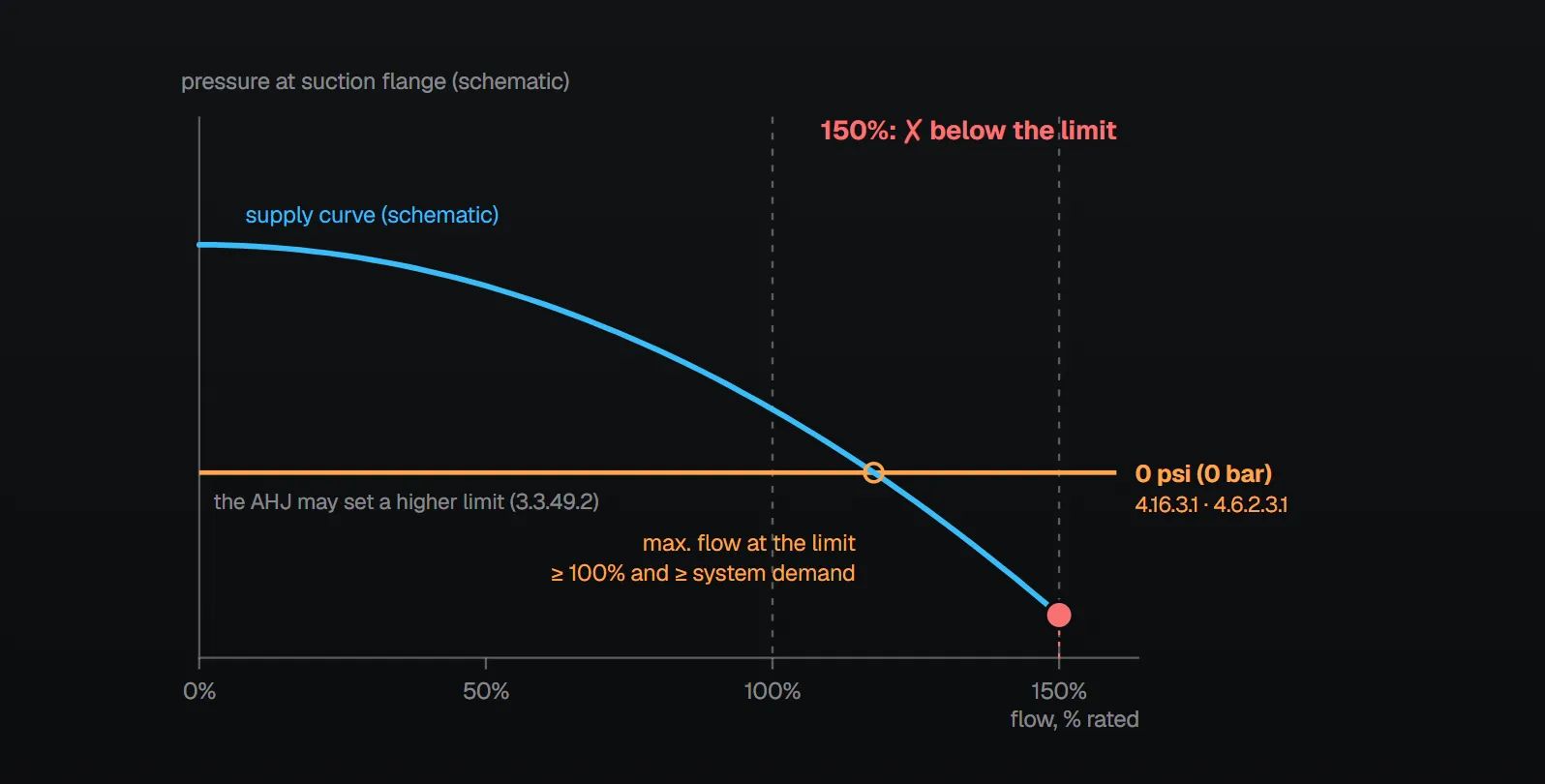
In short: with all pumps at maximum flow, the gauge pressure at the suction flange is 0 psi (0 bar) or higher (4.16.3.1). For a suction tank whose level, after supplying the most demanding system for the required duration, is at or above the pump centreline, that rule does not apply provided the flange pressure does not drop below −3 psi (−0.2 bar) at 150 percent flow at the lowest water level (4.16.3.2). A main that cannot give 150 percent at the lowest permissible suction pressure but can give the greater of 100 percent of rated flow or the system demand is deemed adequate (4.6.2.3.1). The centrifugal pumps of Chapter 6 are not used where a static suction lift is required (6.1.1.4).
Lowest permissible suction pressure
The standard defines it as the lowest suction pressure permitted by the standard and the AHJ (3.3.49.2). Annex A.3.3.49.2 (informative): the AHJ limit will likely apply upstream of the backflow prevention device or at the connection to the water utility main; the permissible pressure at the pump suction could be lower and is found by adding the friction loss and elevation change between that point and the pump suction.
NFPA 20 Handbook (2022) commentary: many jurisdictions have a 20 psi (1.3 bar) suction pressure limitation, used as a precaution against possible cavitation of the underground piping, while NFPA 20 itself allows 0 psi at the flange and −3 psi under the tank conditions. 20 psi is not a suction limit in the standard; there it appears only for the suction gauge: where the minimum suction pressure is below 20 psi (1.3 bar) under any flow, the suction gauge is a compound pressure and vacuum gauge (4.12.2.1.1).
General rule: 0 psi
The suction pipe of a single pump, or the suction header of pumps operating together, is sized so that with all pumps at maximum flow the gauge pressure at the suction flanges is 0 psi (0 bar) or higher. Maximum flow is 150 percent of rated capacity or the maximum flow available from the supply at the lowest permissible suction pressure (4.16.3.1). The head available from the supply is figured at 150 percent of rated capacity (4.6.5.1) and shown by a flow test (4.6.5.3); unless the AHJ permits otherwise, the flow test is not more than 12 months older than the submission of working plans (4.6.1.2).
Suction tank exception: −3 psi
The 0 psi rule does not apply where both conditions are met (4.16.3.2):
- The supply is a suction tank whose water level, after supplying the most demanding system for the required duration, is at or above the elevation of the pump centreline.
- At the tank’s lowest water level, the gauge pressure at the suction flange does not drop below −3 psi (−0.2 bar) at 150 percent of rated flow.
Annex A.4.16.3.2: the negative value allows for friction loss in the suction piping with the pump at 150 percent capacity. NFPA 20 Handbook (2022) commentary: horizontal shaft fire pumps are not permitted to draft water, and −3 psi applies only after the tank has provided the full demand and duration. Because most acceptance tests are run with a full tank, the head from the extra water level is subtracted from the test result when checking the −3 psi condition.
When the main cannot give 150 percent
- Where the main cannot provide 150 percent of rated flow at the lowest permissible suction pressure but can provide the greater of 100 percent of rated flow or the system demand at that pressure, the supply is deemed adequate (4.6.2.3.1). Annex A.4.6.2.3.1: maximum flow is then the highest flow the supply can achieve at the lowest permissible suction pressure.
- The head available may then be calculated at that maximum flow (4.6.5.2).
- The flow at the pump discharge at the lowest permissible suction pressure is at least 100 percent of rated flow (4.6.2.3.2), and the flow and pressure at the discharge meet the maximum fire protection demand (4.6.2.3.3).
For the 150 percent point and the churn limit on the pump curve, see fire pump curve: churn and 150 percent.
Centrifugal pumps and positive pressure
- The centrifugal pumps of Chapter 6 are not used where a static suction lift is required (6.1.1.4). Annex A.6.1.1.4: the centrifugal pump is suited to boosting pressure from a public or private supply or pumping from a storage tank with a positive static head.
- Where the supply is below the discharge flange centreline and its pressure is insufficient to deliver water to the pump, a vertical shaft turbine-type pump is used (7.1.1).
- Pumps with mechanical seals take water from a public main, clean water in a closed-top tank, or a supply meeting the manufacturer’s water quality specification (4.6.2.1.1); the clean water flush for the seals is at positive pressure (4.6.2.1.2). Annex A.4.6.2.1.1: such pumps should operate with positive pressure at the inlet at all times.
Maintaining and monitoring suction pressure
- Suction pressure regulating valve: where the AHJ requires positive pressure on the suction, a valve listed for fire pump service and suction pressure sensitive is permitted (4.17.10.1). It is installed per the manufacturer between the pump and the discharge check valve (4.17.10.2), is not smaller than the discharge size in Section 4.28 (4.17.10.3), its fully open friction loss is included in the design (4.17.10.4), and it is fully open at the system design point and at 100 percent of rated flow (4.17.10.5). Its sensing line may connect to the suction pipe (4.16.9.2(2)).
- Variable speed pump in suction control mode: below rated speed it keeps suction pressure at or above the lowest permissible suction pressure with an accuracy of −0/+3 psi (−0/+0.2 bar) (6.2.2.3).
- Signal: a device that signals when suction pressure or water level falls below a predetermined minimum is permitted (4.16.9.2(3)). A device that stops the pump or restricts its discharge is not installed in the suction (4.16.9.1, Annex A.4.16.9). Handbook (2022) commentary: the signal does not allow the pump to be shut off on low suction pressure.
- Backflow preventer: the final arrangement provides effective pump performance at the lowest permissible suction pressure (4.29.4.1.2), and a retrofitted backflow preventer does not reduce suction pressure below the permitted value (4.29.4.1.6). See suction valves and backflow preventer.
Common field errors
- Applying the AHJ limit directly at the pump flange; per Annex A.3.3.49.2 it usually applies at the main connection or upstream of the backflow preventer.
- Judging −3 psi from a full-tank test without subtracting the extra tank level (Handbook commentary).
- Installing a device that stops the pump on low suction pressure (4.16.9.1).
- Undersizing the suction pipe: the 0 psi condition at the flange depends directly on suction friction loss (4.16.3.1); for pipe rules see suction pipe: elbows and reducers.
Checklist
- Is the AHJ’s lowest suction pressure, and the point where it applies, known (3.3.49.2, Annex A.3.3.49.2)?
- Is the flow test not more than 12 months old (4.6.1.2)?
- Is ≥ 0 psi (0 bar) at the flange shown at maximum flow (4.16.3.1)?
- For a suction tank: is the level after the demand at or above the pump centreline, and ≥ −3 psi (−0.2 bar) at 150 percent (4.16.3.2)?
- If the main cannot give 150 percent: does it give the greater of 100 percent of rated flow or the system demand (4.6.2.3.1)?
- If the minimum suction pressure falls below 20 psi (1.3 bar), is the suction gauge a compound gauge (4.12.2.1.1)?
Frequently Asked Questions
What is the minimum fire pump suction pressure?
With all pumps at maximum flow, 0 psi (0 bar) gauge or higher at the suction flange (NFPA 20-2025 4.16.3.1). The AHJ may set a higher lowest permissible suction pressure (3.3.49.2).
When may suction pressure drop to −3 psi?
From a suction tank whose level, after supplying the most demanding system for the required duration, is at or above the pump centreline, provided the flange pressure does not drop below −3 psi (−0.2 bar) at 150 percent flow at the lowest level (4.16.3.2). Annex A.4.16.3.2: the value allows for suction pipe friction loss.
Can a pump be used if the main cannot give 150 percent flow?
Yes, if at the lowest permissible suction pressure the main gives the greater of 100 percent of rated flow or the system demand (4.6.2.3.1); at least 100 percent of rated flow is available at the discharge (4.6.2.3.2).
Does NFPA 20 set a 20 psi suction limit?
Not as a suction limit. NFPA 20 Handbook (2022) commentary notes that many jurisdictions apply 20 psi (1.3 bar). In the standard, 20 psi (1.3 bar) appears only as the trigger for a compound suction gauge (4.12.2.1.1).
Can the pump shut down automatically on low suction pressure?
No. Devices that stop the pump or restrict its discharge are not installed in the suction (4.16.9.1, Annex A.4.16.9); a signalling device is permitted (4.16.9.2(3)). Where positive pressure is required, a listed suction pressure regulating valve may be used on the discharge side (4.17.10).

SprinkCalc — Fire Sprinkler Design Across Three Standards
SprinkCalc covers hazard classification, design density and area, K-factor selection, water demand and hydraulic calculations for NFPA 13, FM Global and BS EN 12845 in a single iOS app, and exports a professional PDF report.
Download SprinkCalc on the App Store
MEP Calc — 110+ Engineering Calculators
MEP Calc bundles 110+ engineering modules in one iOS app: 21 fire calculations plus heating, cooling, HVAC, plumbing, steam and natural gas.
Download MEP Calc on the App StoreNFPA 20-2025, Standard for the Installation of Stationary Pumps for Fire Protection: 3.3.49.2; 4.6.1.2, 4.6.2.1.1, 4.6.2.1.2, 4.6.2.3.1–4.6.2.3.3, 4.6.5.1–4.6.5.3; 4.12.2.1.1; 4.16.3.1, 4.16.3.2, 4.16.9.1, 4.16.9.2; 4.17.10.1–4.17.10.5; 4.29.4.1.2, 4.29.4.1.6; 6.1.1.4, 6.2.2.3; 7.1.1; Annex A.3.3.49.2, A.4.6.2.1.1, A.4.6.2.3.1, A.4.16.3.2, A.4.16.9, A.6.1.1.4 (informative). NFPA 20 Handbook 2022 commentary on 3.3.49.2, 4.6.2.3.1, A.4.16.3.2 and 4.16.9.2(3).