Fire pumps are often chosen by looking only at the flow and pressure on the nameplate. NFPA 20-2025, however, places two limits on the whole characteristic curve of a centrifugal pump: a ceiling on head at shutoff (churn) and a floor at 150% of rated capacity. This article covers the rated point, those two limits and the demand range the pump should be selected for, clause by clause.
In short: a pump furnishes not less than 150% of rated capacity at not less than 65% of total rated head (6.2.1). Shutoff (churn) head may not exceed 140% of rated head for any type of pump (6.2.2). The greatest single demand of any system connected to the pump may not exceed 150% of rated capacity (4.10.1). Annex A adds that above 140% suction conditions can affect performance and that application below 90% is not recommended (A.4.10).
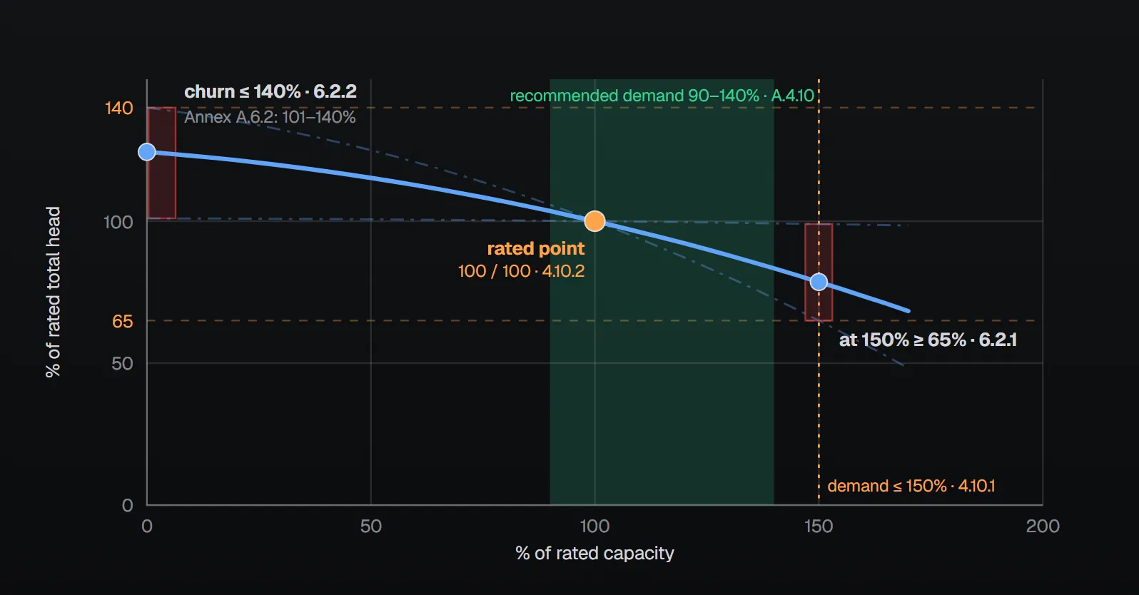
Three points on the curve
The standard states the limits as percentages; absolute values follow from the pump’s rated capacity and rated pressure.
| Point | Flow | Head | Clause |
|---|---|---|---|
| Churn (shutoff) | 0 | At most 140% of rated head | 6.2.2 |
| Rated point | 100% (one of the values in Table 4.10.2) | Rated head; net pressure 40 psi (2.7 bar) or more | 4.10.2 |
| Overload | 150% | At least 65% of total rated head | 6.2.1 |
The same two limits apply to vertical shaft turbine pumps (7.1.2.1, 7.1.2.2). On a multistage multiport pump each discharge outlet meets both separately (6.2.1.1, 6.2.2.1).
Annex A.6.2 (explanatory) notes that listed pumps can have different curve shapes for the same rating: shutoff head ranges from a minimum of 101% to a maximum of 140% of rated head, and head at 150% of rated capacity from a minimum of 65% to a maximum of just below rated head. Figure A.6.2 draws the two extremes as the “steepest shape permissible” and the “flat” curve. The manufacturer supplies the expected curve and furnishes certified shop test curves of head–capacity and brake horsepower to the purchaser (4.5.1).
Example: a 1500 gpm, 100 psi pump
The NFPA 20 Handbook (2022) commentary illustrates Figure A.6.2 with a pump rated 1500 gpm (5677 L/min) at 100 psi (6.9 bar). For that pump the limits read as follows:
- Churn: at most 140 psi (9.7 bar) (6.2.2). The handbook says that, without a manufacturer’s curve, the churn point can be estimated for plotting at midrange, 120% of rated pressure, and uses 120 psi in its example.
- 150% flow: at least 65 psi (4.5 bar) at 2250 gpm (8516 L/min) (6.2.1).
The handbook also reminds that the suction pressure is added to the pump curve to obtain the discharge curve, and that all system components must be rated for the maximum pressure the pump develops.
What demand is the pump selected for?
The rule is a single upper limit: the greatest single demand of any fire protection system connected to the pump must be less than or equal to 150% of rated capacity (4.10.1). Rated capacity is one of the 21 values in Table 4.10.2, from 25 gpm (95 L/min) to 5000 gpm (18,925 L/min), and the pump is rated at net pressures of 40 psi (2.7 bar) or more (4.10.2). Pumps rated over 5000 gpm (18,925 L/min) are subject to individual review by the authority having jurisdiction or a listing laboratory (4.10.3). Annex A.4.10.2 notes that the metric values in the table are soft conversions because there are no standardized metric flow ratings.
Annex A.4.10 adds two recommendations: performance at capacities over 140% of rated can be adversely affected by suction conditions, and application below 90% of rated capacity is not recommended. It also asks that selection not be confused with operating conditions: with proper suction conditions the pump can operate at any point on its curve from shutoff to 150%.
The NFPA 20 Handbook (2022) commentary explains why: a demand between 90% and 140% keeps the pump from being oversized and from running at its maximum output. After years of service a pump may wear and no longer reach 150%; a pump selected on its 150% point would eventually fall short. A demand below 90% means the pump is too large for the system, with higher power supply demand and more water used in testing.
Why is churn limited?
Churn pressure sets the highest pressure in the installation. Net churn pressure plus the maximum static suction pressure, adjusted for elevation, may not exceed the pressure rating of the system components (4.7.7.1). Pressure relief valves and pressure-regulating devices in the fire pump installation may not be used to meet this (4.7.7.2). Annex A.4.7.7 states that a relief valve is not an acceptable method of reducing system pressure under normal operating conditions, and that before the 2003 edition the practice was not strictly prohibited, so such installations may still be in service. Variable speed pumps are acceptable to limit system pressure (4.7.7.3.1). When a main relief valve is needed is covered in a separate article.
At churn no water flows, yet the pump keeps turning. Per the Handbook (2022) commentary, a centrifugal pump reaches a maximum pressure against a closed system and can run indefinitely provided enough water is discharged to cool it; the energy given to the water turns into heat. Annex A.3.3.43 likewise says a small discharge is required to prevent overheating under no-flow conditions; the circulation relief valve does this (4.13).
Beyond 150%: driver power
The nameplate shows the maximum pump horsepower needed at any flow, including flows beyond 150% of rated capacity (4.11.3). The driver is selected to run the pump at rated speed and maximum pump load under any flow condition (4.7.6). Per Annex A.4.7.6, maximum brake horsepower for centrifugal and turbine pumps typically occurs beyond 150% of rated capacity. Annex A.3.3.47 adds that peak power usually occurs between 130% and 150% and may keep rising beyond 150%, but NFPA 20 does not require testing beyond 150%.
Suction side and acceptance test
The head available from a water supply is figured on the basis of 150% of rated capacity (4.6.5.1). Where the supply cannot provide 150% at the lowest permissible suction pressure but can provide the greater of 100% of rated flow or the system demand, the head may be calculated on the maximum flow available at that pressure (4.6.5.2), as shown by a flow test (4.6.5.3). See minimum suction pressure for the limits.
The pump, driver and controller must perform as an entire unit in compliance with the standard and be field acceptance tested (4.4.1, 4.4.2). In the acceptance test, minimum, rated and peak loads are set by controlling the water discharged through approved test devices (14.2.6.3.3). Where the supply cannot provide 150%, the pump is run at the greater of 100% of rated flow or the maximum system demand (14.2.6.3.4). For the test arrangement see test header and flowmeter.
Common field mistakes
- Using a relief valve to cut churn: prohibited by 4.7.7.2; Annex A.4.7.7 calls it not acceptable.
- Placing the demand at 150%: the Handbook (2022) notes a worn pump may eventually not reach 150%, creating a deficiency.
- Oversizing the pump: a demand below 90% of rated capacity is not recommended (A.4.10).
- Judging test results only against 140% / 65%: per the Handbook (2022), NFPA 20 requires performance to be measured against the original pump curve; the limits are used when the original curve is not available.
Checklist
- Manufacturer’s certified shop test curves (head–capacity, brake horsepower) on file (4.5.1).
- Rated capacity from Table 4.10.2; net pressure 40 psi (2.7 bar) or more (4.10.2).
- Churn at most 140% of rated head (6.2.2).
- At least 65% head at 150% flow (6.2.1).
- Greatest single demand not over 150% of rated capacity (4.10.1); recommended 90–140% (A.4.10).
- Net churn + maximum static suction pressure (elevation-adjusted) within component ratings, without relying on a relief valve (4.7.7.1, 4.7.7.2).
- Nameplate shows maximum pump horsepower including flows beyond 150% (4.11.3).
Frequently Asked Questions
What is churn pressure and what is its limit?
It is the pressure the pump develops at shutoff, with no flow. Shutoff head may not exceed 140% of rated head for any type of pump (NFPA 20-2025 6.2.2); the same limit applies to vertical turbine pumps (7.1.2.2).
How much pressure must a pump deliver at 150% flow?
At least 65% of total rated head (6.2.1). For example, a pump rated at 100 psi (6.9 bar) delivers at least 65 psi (4.5 bar) at 150% flow.
Can the system demand exceed the pump’s rated flow?
Yes, provided the greatest single demand does not exceed 150% of rated capacity (4.10.1). Annex A.4.10 notes suction conditions can affect performance above 140% and does not recommend application below 90%.
If churn is high, can a relief valve be added?
No. Pressure relief valves and pressure-regulating devices may not be used to keep net churn plus maximum static suction pressure within component ratings (4.7.7.1, 4.7.7.2). Variable speed pumps are acceptable to limit system pressure (4.7.7.3.1).
Which point is the driver sized for?
For the power needed to run the pump at rated speed and maximum pump load under any flow condition (4.7.6). Maximum brake horsepower typically occurs beyond 150% (A.4.7.6) and is shown on the nameplate (4.11.3).

SprinkCalc — Fire Sprinkler Design Across Three Standards
SprinkCalc covers hazard classification, design density and area, K-factor selection, water demand and hydraulic calculations for NFPA 13, FM Global and BS EN 12845 in a single iOS app, and exports a professional PDF report.
Download SprinkCalc on the App Store
MEP Calc — 110+ Engineering Calculators
MEP Calc bundles 110+ engineering modules in one iOS app: 21 fire calculations plus heating, cooling, HVAC, plumbing, steam and natural gas.
Download MEP Calc on the App StoreNFPA 20-2025, Standard for the Installation of Stationary Pumps for Fire Protection: 4.4.1, 4.4.2; 4.5.1; 4.6.5.1–4.6.5.3; 4.7.6; 4.7.7.1, 4.7.7.2, 4.7.7.3.1; 4.10.1–4.10.3, Table 4.10.2; 4.11.3; 6.2.1, 6.2.1.1, 6.2.2, 6.2.2.1; 7.1.2.1, 7.1.2.2; 14.2.6.3.3, 14.2.6.3.4; Annex A.3.3.43, A.3.3.47, A.4.7.6, A.4.7.7, A.4.10, A.4.10.2, A.6.2, Figure A.6.2 (explanatory). NFPA 20 Handbook 2022 commentary: Sections 4.10 and 6.2.