NFPA 20-2025 limits which valve type the suction pipe carries, how close it may be to the suction flange, and when and how far away a check valve or backflow preventer may be installed in the suction (4.16.5, 4.16.9, 4.29).
In short: a listed OS&Y gate valve is installed in the suction pipe (4.16.5.1). Within 50 ft (15.3 m) of the suction flange, no control valve other than a listed OS&Y valve and the devices permitted in 4.29.3 is installed (4.16.5.4), so a butterfly valve stays out of that zone. Check valves and backflow preventers go in the suction only where another NFPA standard or the AHJ requires them (4.16.9.2(1)); there they are at least 10 pipe diameters from the flange (4.29.3), and a backflow preventer with butterfly control valves at least 50 ft (15.2 m) along the route of pipe (4.29.3.1). Annex A.4.16.9 prefers the discharge side for a backflow preventer.
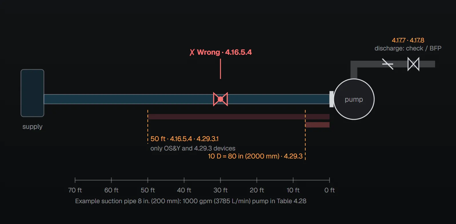
Suction valve: OS&Y and 50 ft
- A listed outside screw and yoke (OS&Y) gate valve is installed in the suction pipe (4.16.5.1).
- Listed indicating valves and valves with an automatic means of operation do not close in less than 5 seconds when operated at maximum possible speed from fully open (4.16.5.2.1, 4.16.5.2.2).
- A listed indicating valve with automated controls is permitted; it has reliable position indication and a valve supervisory switch connected to a remote supervisory station, and operates manually as well as automatically (4.16.5.3.1, 4.16.5.3.2).
- No control valve other than a listed OS&Y valve and the devices permitted in 4.29.3 is installed within 50 ft (15.3 m) of the pump suction flange (4.16.5.4).
- Where provided, the suction valve, discharge valve, bypass valves and the isolation valves on the backflow preventer are supervised open: central, proprietary or remote station signalling; a local signal at a constantly attended point; locking; or sealing with approved weekly recorded inspection inside owner-controlled fenced enclosures (4.18.1).
Why
Annex A.4.16.5 (informative): from public mains the gate valve should be as far as practical from the pump suction flange; from a stored supply, at the container outlet. A butterfly valve on the suction side can create turbulence that adversely affects pump performance and can increase the possibility of blockage. NFPA 20 Handbook (2022) commentary: the gate of an OS&Y valve is outside the waterway when fully open, while the disc of a butterfly valve is always in the pipe and causes turbulence; at 50 ft (15.3 m) or more the turbulence dies out before the water reaches the suction flange.
Devices permitted in the suction
No device or assembly that will stop, restrict the starting of, or restrict the discharge of a fire pump or driver is installed in the suction piping, except those listed in 4.16.9.2 (4.16.9.1):
- Check valves and backflow prevention devices, where required by other NFPA standards or the AHJ, installed per Section 4.29.
- Where the AHJ requires positive pressure on the suction, a sensing line for a low suction pressure control specifically listed for fire pump service.
- Devices that activate a signal if suction pressure or water level falls below a predetermined minimum.
- Suction strainers where required by other sections of the standard.
- A listed suction diffuser.
- Other devices specifically permitted or required by the standard (4.16.9.2).
Annex A.4.16.9: “device” here includes devices that sense suction pressure and then restrict or stop the pump discharge.
Check valves and backflow preventers: position and relief
| Rule | Value | Clause |
|---|---|---|
| Listing | Listed for fire protection service | 4.29.1 |
| Check valve or backflow preventer in the suction | At least 10 pipe diameters from the suction flange | 4.29.3 |
| Backflow preventer with butterfly control valves in the suction | At least 50 ft (15.2 m), measured along the route of pipe | 4.29.3.1 |
| Backflow preventer relief valve | Discharges to a drain sized for the maximum anticipated flow; air gap per manufacturer; discharge readily visible or detectable; documented by calculations and tests | 4.29.2.1–4.29.2.4 |
| Discharge side | Listed check valve or backflow preventer in the discharge assembly; listed indicating gate or butterfly valve on the system side of the check valve | 4.17.7, 4.17.8 |
A butterfly valve is not installed between pumps in series (4.17.9).
Evaluating the backflow preventer loss
- Where a backflow preventer is installed with the pump, special consideration is given to the added pressure loss (4.29.4.1.1).
- The final arrangement provides effective pump performance at the lowest permissible suction pressure (4.29.4.1.2).
- The discharge flow meets or exceeds the system design flow and 100 percent of rated pump flow (4.29.4.1.3, 4.29.4.1.4), documented by calculations and tests (4.29.4.1.5).
- A retrofitted backflow preventer does not reduce suction pressure below that permitted by the standard and accepted by the AHJ, and does not leave a discharge pressure that fails the maximum system demand and 100 percent of rated flow (4.29.4.1.6, 4.29.4.1.7).
Why the discharge side
Annex A.4.16.9: because of pressure losses and the potential to interrupt flow to the fire protection systems, backflow prevention devices are discouraged in fire pump piping; where required, placing one on the discharge side keeps acceptable flow to the pump suction, since it is more efficient to lose pressure after the pump has boosted it. With a discharge-side backflow preventer and a jockey pump, the jockey discharge and sensing lines are located so that no cross-connection is created through the jockey pump. Annex A.4.17.7: where a backflow preventer replaces the discharge check valve, an additional one might be necessary in the bypass piping.
NFPA 20 Handbook (2022) commentary: water leaving a backflow preventer is extremely turbulent; 10 pipe diameters is the distance accepted in the water control industries for that turbulence to settle. The handbook also shows with a worked example how the friction loss of a suction-side backflow preventer can take the suction flange pressure below zero.
Common field errors
- A butterfly valve within 50 ft of the suction flange (4.16.5.4; Annex A.4.16.5).
- A check valve or backflow preventer closer than 10 pipe diameters to the flange; the NFPA 20 Handbook (2022) pictures such a double check assembly (4.29.3).
- A backflow preventer with butterfly valves within 50 ft in the suction (4.29.3.1).
- A suction valve not supervised open (4.18.1). Handbook commentary: closed valves continue to be the leading cause of fire protection system failure.
- A retrofitted backflow preventer whose pressure loss was not evaluated (4.29.4.1.6).
Checklist
- Is there a listed OS&Y gate valve in the suction (4.16.5.1)?
- Is any control valve other than OS&Y within 50 ft (15.3 m) of the flange (4.16.5.4)?
- Is the suction check valve or backflow preventer required by an NFPA standard or the AHJ (4.16.9.2(1))?
- Is it at least 10 pipe diameters away, or 50 ft with butterfly valves (4.29.3, 4.29.3.1)?
- Are relief drain, air gap and visibility in order (4.29.2)?
- Is performance at the lowest permissible suction pressure documented by calculations and tests (4.29.4.1.2, 4.29.4.1.5)?
- Are the valves supervised open (4.18.1)?
Frequently Asked Questions
Can a butterfly valve be used in a fire pump suction?
No control valve other than a listed OS&Y valve and the devices of 4.29.3 is installed within 50 ft (15.3 m) of the suction flange (NFPA 20-2025 4.16.5.4). Annex A.4.16.5 notes that a suction-side butterfly valve can create turbulence that adversely affects pump performance.
How far from the suction flange must a backflow preventer be?
A check valve or backflow preventer in the suction is at least 10 pipe diameters from the flange (4.29.3); one with butterfly control valves at least 50 ft (15.2 m) along the route of pipe (4.29.3.1).
Should the backflow preventer go on the suction or the discharge?
NFPA 20 does not mandate the location; it goes in the suction only where another NFPA standard or the AHJ requires it (4.16.9.2(1)). Annex A.4.16.9 prefers the discharge side because of pressure losses: it is more efficient to lose pressure after the pump has boosted it.
How fast may a suction valve close?
Listed indicating valves and automatically operated valves do not close in less than 5 seconds at maximum possible speed from fully open (4.16.5.2.1, 4.16.5.2.2).
Can a device stop the pump on low suction pressure?
No. Devices that stop, restrict the starting of, or restrict the discharge of the pump are not installed in the suction (4.16.9.1); Annex A.4.16.9 includes devices that sense suction pressure and restrict or stop discharge. A device that only signals low pressure is permitted (4.16.9.2(3)).

SprinkCalc — Fire Sprinkler Design Across Three Standards
SprinkCalc covers hazard classification, design density and area, K-factor selection, water demand and hydraulic calculations for NFPA 13, FM Global and BS EN 12845 in a single iOS app, and exports a professional PDF report.
Download SprinkCalc on the App Store
MEP Calc — 110+ Engineering Calculators
MEP Calc bundles 110+ engineering modules in one iOS app: 21 fire calculations plus heating, cooling, HVAC, plumbing, steam and natural gas.
Download MEP Calc on the App StoreNFPA 20-2025, Standard for the Installation of Stationary Pumps for Fire Protection: 4.16.5.1–4.16.5.4, 4.16.9.1, 4.16.9.2; 4.17.7–4.17.9; 4.18.1; 4.29.1, 4.29.2.1–4.29.2.4, 4.29.3, 4.29.3.1, 4.29.4.1.1–4.29.4.1.7; Annex A.4.16.5, A.4.16.9, A.4.17.7 (informative). NFPA 20 Handbook 2022 commentary: Section 4.16 (commentary on 4.16.5, 4.16.9.1, 4.16.9.2) and Section 4.29 (commentary on 4.29.2.3).