For the fire pump suction pipe, NFPA 20-2025 Section 4.16 sets the suction pipe size, the plane in which elbows and tees near the flange may lie, and the reducer to use at a change of size. This article summarises those rules for a horizontal split-case pump, with clause numbers.
In short: the suction pipe is sized so that, with all pumps at maximum flow, the gauge pressure at the suction flange is 0 psi (0 bar) or higher (4.16.3.1); the portion within 10 pipe diameters of the flange is not smaller than the size in Section 4.28 (4.16.3.3). On a horizontal split-case pump, elbows and tees with a centreline plane parallel to the pump shaft are not permitted unless the flange-to-flange distance is greater than 10 pipe diameters (4.16.6.3.1, 4.16.6.3.2); elbows perpendicular to the shaft are permitted anywhere (4.16.6.3.3). Where pipe and flange sizes differ, an eccentric tapered reducer is installed so as to avoid air pockets (4.16.6.4).
Where the suction components start
Suction components are all pipe, valves and fittings from the pump suction flange to the connection to the water service main, storage tank or reservoir that feeds the pump (4.16.1.1). For pumps in series, the suction pipe of the next pump begins at the system side of the previous pump’s discharge valve (4.16.1.2). Suction pipe is installed and tested in accordance with NFPA 24 (4.16.2).
Size: the 0 psi rule and Table 4.28
The suction pipe of a single pump, or the suction header of pumps designed to operate together, is sized so that with all pumps at maximum flow the gauge pressure at the suction flanges is 0 psi (0 bar) or higher. Maximum flow is 150 percent of rated capacity or the maximum flow available from the supply at the lowest permissible suction pressure (4.16.3.1). For the suction tank exception down to −3 psi (−0.2 bar), see fire pump minimum suction pressure (4.16.3.2).
The portion within 10 pipe diameters upstream of the flange is not smaller than the size in Section 4.28 (4.16.3.3). Table 4.28 sizes are minimums (4.28); its footnotes state that the suction sizes are based on a maximum velocity of 15 ft/s (4.6 m/s) at 150 percent of rated capacity in most cases, and that the pump flange may differ from the pipe size.
| Pump rating | Minimum suction pipe · Table 4.28(a) | Minimum suction pipe · Table 4.28(b) |
|---|---|---|
| 500 gpm (1,892 L/min) | 5 in. | 125 mm |
| 750 gpm (2,839 L/min) | 6 in. | 150 mm |
| 1,000 gpm (3,785 L/min) | 8 in. | 200 mm |
| 1,250 gpm (4,731 L/min) | 8 in. | 200 mm |
| 1,500 gpm (5,677 L/min) | 8 in. | 200 mm |
| 2,000 gpm (7,570 L/min) | 10 in. | 250 mm |
| 2,500 gpm (9,462 L/min) | 10 in. | 250 mm |
| 3,000 gpm (11,355 L/min) | 12 in. | 300 mm |
| 3,500 gpm (13,247 L/min) | 12 in. | 300 mm |
| 4,000 gpm (15,140 L/min) | 14 in. | 350 mm |
| 4,500 gpm (17,032 L/min) | 16 in. | 400 mm |
| 5,000 gpm (18,925 L/min) | 16 in. | 400 mm |
NFPA 20 Handbook (2022) commentary: the velocity limit is there to limit turbulence; turbulent flow generates air bubbles that reduce pump efficiency. The same commentary notes that a common suction pipe is sized for all pumps designed to run simultaneously, and that redundant pumps installed for reliability are not counted. Where one suction pipe supplies more than one pump, the layout gives each pump its proportional supply (4.16.7).
Elbows and tees: plane and 10 pipe diameters
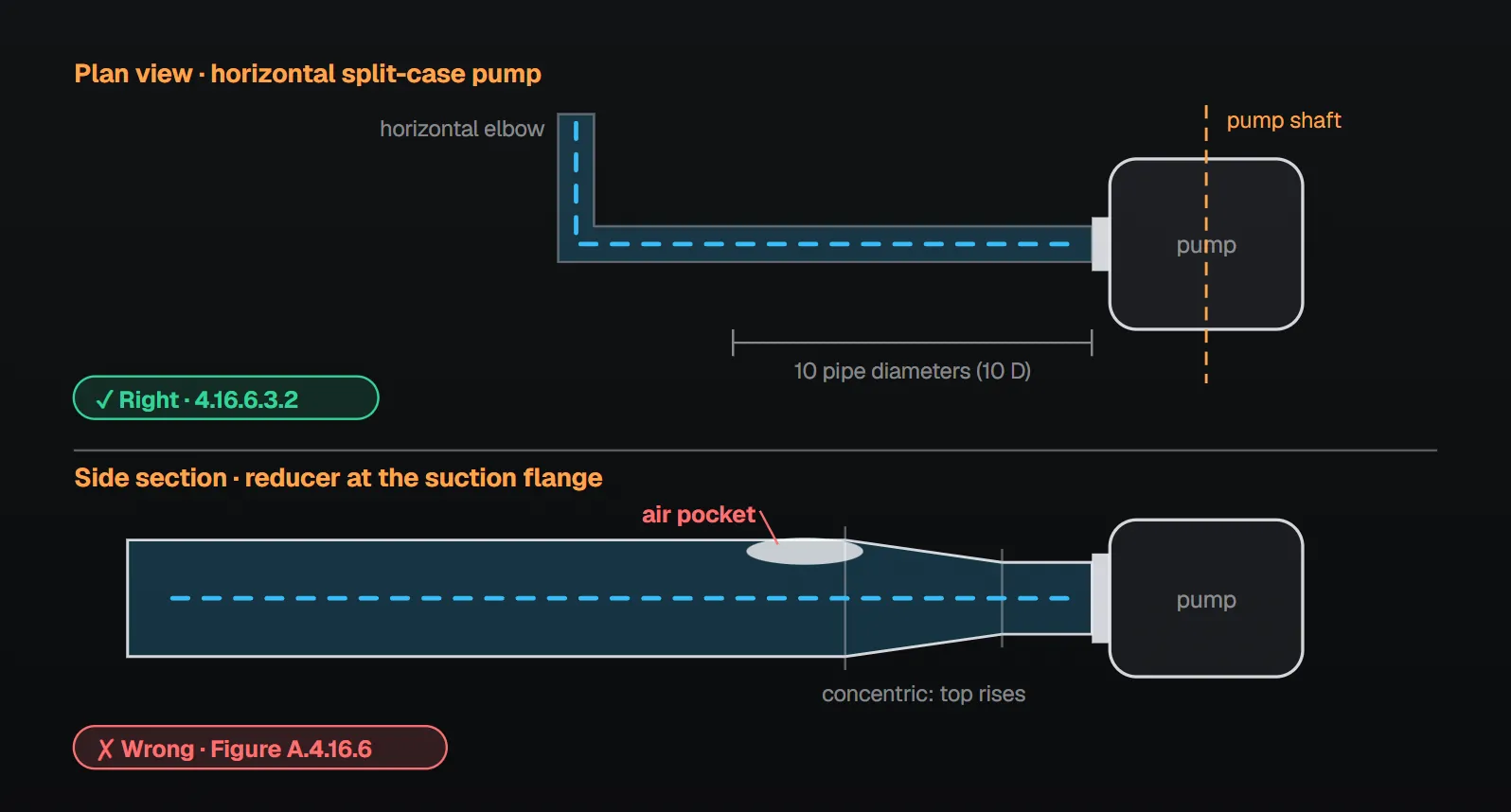
- On a horizontal split-case pump, elbows and tees with a centreline plane parallel to the pump shaft are not permitted (4.16.6.3.1).
- This does not apply where the distance between the pump suction flange and the elbow or tee flange is greater than 10 times the suction pipe diameter (4.16.6.3.2).
- Elbows and tees with a centreline plane perpendicular to the shaft are permitted at any location in the suction (4.16.6.3.3).
- A listed suction diffuser is permitted in the fire pump suction (4.16.9.2(5)).
Because the shaft is horizontal, a plane parallel to it is in practice an elbow turning in the horizontal plane; a plane perpendicular to it is an elbow where the pipe rises or drops and turns in the vertical plane. Figure A.4.16.6 (Annex A, informative) draws these right and wrong suction layouts.
Why
The clause gives no reason. NFPA 20 Handbook (2022) commentary: a parallel-plane elbow within 10 pipe diameters sends unbalanced flow into the impeller; this puts an axial load on the shaft and bearings, causing bearing wear and pump damage over time, and severe cavitation if not corrected. The commentary adds that the rule is for horizontal split-case pumps only; in a vertical in-line pump gravity already creates an axial imbalance. The handbook recommends, but NFPA 20 does not require, a long-radius elbow in the perpendicular plane to reduce turbulence, and notes that a suction diffuser can remove the need to meet the 10 pipe diameter rule.
Which diameter sets 10 D
The clause refers to the suction pipe diameter (4.16.6.3.2). NFPA 20 Handbook (2022) commentary reads this as the suction pipe size in Table 4.28: for a 1000 gpm (3785 L/min) pump with an 8 in. (200 mm) suction pipe, a parallel-plane elbow sits 80 in. (2000 mm) from the suction flange, even if the pump flange is 6 in. (150 mm).
Eccentric reducer and the air pocket
Where the suction pipe and the pump suction flange are not the same size, they are joined by an eccentric tapered reducer or increaser installed so as to avoid air pockets (4.16.6.4). The general rule is that suction pipe is laid carefully to avoid air leaks and air pockets, either of which can seriously affect pump operation (4.16.6.1). Figure A.4.16.6 marks the air pocket at the top of a concentric reducer as “wrong”. Chapter 6 also lists an eccentric tapered reducer at the suction inlet among the fittings provided where necessary (6.3.2).
NFPA 20 Handbook (2022) commentary: when the pump is fed from below or from the horizontal plane, the flat side of the reducer is on top and the reduction is at the bottom; when fed from above, the flat side on the bottom is recommended. The handbook also advises avoiding trapped pipe sections that collect air, notes that air pockets intensify corrosion and can interfere with flow into the impeller, and recommends automatic air release valves on such sections.
Other suction pipe rules
- Suction pipe is installed below the frost line or in frostproof casings (4.16.6.2.1).
- Where the pump and its suction supply are on separate foundations with rigid pipe between them, the pipe has strain relief (4.16.6.5).
- With a tank suction, the tank outlet has a vortex-control assembly per NFPA 22 (4.16.10).
- Valves and devices in the suction pipe are restricted; see suction valves and backflow preventer (4.16.5, 4.16.9).
Common field errors
- A horizontal-plane elbow closer than 10 pipe diameters to the flange. The NFPA 20 Handbook (2022) shows such an elbow as “installed in the incorrect plane” (4.16.6.3.1).
- A concentric reducer, or an eccentric one installed upside down: the air pocket of Figure A.4.16.6 (4.16.6.4).
- Measuring 10 D with the pump flange size; the handbook commentary uses the Table 4.28 pipe size.
- Pipe smaller than Table 4.28 within 10 pipe diameters of the flange (4.16.3.3).
Checklist
- Is 0 psi (0 bar) or higher gauge pressure at the suction flange shown with all pumps at maximum flow (4.16.3.1)?
- Is the pipe within 10 pipe diameters of the flange at least the Table 4.28 size (4.16.3.3)?
- Is there an elbow or tee parallel to the shaft; if so, is it more than 10 pipe diameters away (4.16.6.3)?
- Is the size change made with an eccentric tapered reducer that leaves no air pocket (4.16.6.4)?
- Is there any section that can trap air or leak air (4.16.6.1)?
- Does a common suction pipe give each pump its proportional supply (4.16.7)?
Frequently Asked Questions
How close can an elbow be to a fire pump suction flange?
On a horizontal split-case pump, elbows and tees with a centreline plane parallel to the pump shaft are not permitted unless the flange-to-flange distance is greater than 10 suction pipe diameters (NFPA 20-2025 4.16.6.3.1, 4.16.6.3.2). Elbows perpendicular to the shaft are permitted anywhere (4.16.6.3.3).
Is 10 D measured with the pump flange or the suction pipe?
The clause refers to the suction pipe diameter (4.16.6.3.2). NFPA 20 Handbook (2022) commentary uses the Table 4.28 pipe size: with an 8 in. (200 mm) pipe the distance is 80 in. (2000 mm).
Why is an eccentric reducer used on the suction?
Where pipe and pump flange sizes differ, the reducer is an eccentric tapered one installed so as to avoid air pockets (4.16.6.4). Figure A.4.16.6 shows the air pocket above a concentric reducer as wrong; the standard says air pockets can seriously affect pump operation (4.16.6.1).
How is the suction pipe sized?
So that the gauge pressure at the suction flange is 0 psi (0 bar) or higher with all pumps at maximum flow (4.16.3.1); the part within 10 pipe diameters of the flange is not smaller than Table 4.28 (4.16.3.3). Per the table footnote, the sizes are based on 15 ft/s (4.6 m/s) at 150 percent flow in most cases.
Does the 10 pipe diameter rule apply to vertical in-line pumps?
The clause addresses horizontal split-case pumps (4.16.6.3.1). NFPA 20 Handbook (2022) commentary states that the rule applies only to those pumps.

SprinkCalc — Fire Sprinkler Design Across Three Standards
SprinkCalc covers hazard classification, design density and area, K-factor selection, water demand and hydraulic calculations for NFPA 13, FM Global and BS EN 12845 in a single iOS app, and exports a professional PDF report.
Download SprinkCalc on the App Store
MEP Calc — 110+ Engineering Calculators
MEP Calc bundles 110+ engineering modules in one iOS app: 21 fire calculations plus heating, cooling, HVAC, plumbing, steam and natural gas.
Download MEP Calc on the App StoreNFPA 20-2025, Standard for the Installation of Stationary Pumps for Fire Protection: 4.16.1.1, 4.16.1.2, 4.16.2, 4.16.3.1–4.16.3.3, 4.16.6.1–4.16.6.5, 4.16.7, 4.16.9.2(5), 4.16.10; 4.28, Table 4.28(a), 4.28(b) and footnotes; 6.3.2; Annex A.4.16.6, Figure A.4.16.6 (informative). NFPA 20 Handbook 2022 commentary: Section 4.16 (commentary on 4.16.3.1, 4.16.3.3, A.4.16.6, 4.16.6.1, 4.16.6.3, 4.16.9.2(5)).