The two gauges on a fire pump are the only field instruments that show what the pump is doing: the suction gauge reads the pressure at which water reaches the pump, the discharge gauge reads the pump’s outlet pressure. NFPA 20-2025 Section 4.12 sets the dial size, connection point, gauge valve and dial range. This article gives the rules together with the NFPA 20 Handbook (2022) commentary.
In short: discharge and suction gauges have dials at least 3.5 in. (89 mm) in diameter, each connected with a nominal 0.25 in. (6 mm) gauge valve (4.12.1.1, 4.12.2.1). The discharge dial indicates at least twice the pump’s rated working pressure and not less than 200 psi (13.8 bar) (4.12.1.2). Where suction pressure can fall below 20 psi (1.3 bar) at any flow, the suction gauge is a compound pressure and vacuum gauge (4.12.2.1.1), with a range of two times the maximum suction pressure (4.12.2.3).
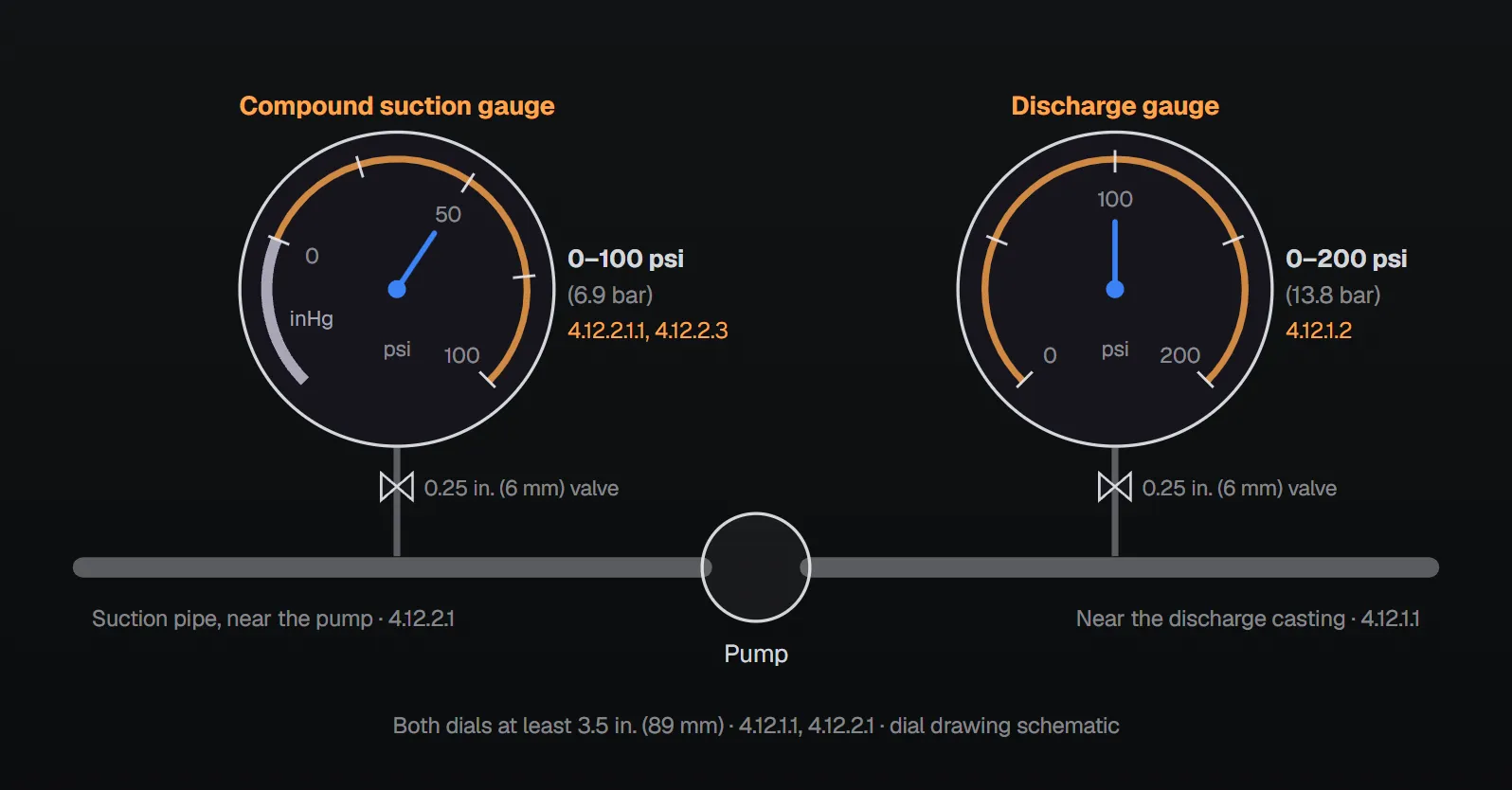
Discharge gauge
| Item | Rule | Clause |
|---|---|---|
| Dial diameter | At least 3.5 in. (89 mm) | 4.12.1.1 |
| Connection point | Near the discharge casting | 4.12.1.1 |
| Gauge valve | Nominal 0.25 in. (6 mm) | 4.12.1.1 |
| Dial range | At least twice the rated working pressure, not less than 200 psi (13.8 bar) | 4.12.1.2 |
| Units | bar, psi or both, with the manufacturer’s standard graduations | 4.12.1.3 |
Example: for a pump rated at 80 psi, twice the rating is 160 psi, so the 200 psi (13.8 bar) minimum governs. For a pump rated at 150 psi, the dial must read at least 300 psi.
Suction gauge
- Dial at least 3.5 in. (89 mm), connected to the suction pipe near the pump with a nominal 0.25 in. (6 mm) gauge valve (4.12.2.1).
- Where the minimum suction pressure is below 20 psi (1.3 bar) under any flow condition, the gauge is a compound pressure and vacuum gauge (4.12.2.1.1).
- For the suction range the dial reads in inches (millimeters) of mercury or psi (bar) (4.12.2.2).
- Its range is two times the rated maximum suction pressure of the pump (4.12.2.3).
- 4.12.2 does not apply to vertical shaft turbine pumps taking suction from a well or open wet pit (4.12.2.4); on these pumps the discharge gauge per 4.12.1 is one of the required fittings (7.3.5.1).
The Handbook (2022) explains the compound gauge: because negative pressures can occur on the suction side, its units can differ from the discharge gauge; positive pressure reads in psi (bar) and vacuum in inches (millimeters) of mercury. It gives 1 inHg = 0.491 psi and 1 mmHg = 0.00133322 bar. For a vertical turbine pump, suction lift is found by measuring the distance from the water level to the discharge gauge.
Why it matters
Per the NFPA 20 Handbook (2022), the suction and discharge gauges measure pressure on both sides of the pump in operation and during the regular no-flow tests required by NFPA 25. Because they are used weekly and sometimes annually, they should be good enough to read reasonably accurately and should be calibrated every year. Liquid-filled gauges are recommended for the most accurate readings; the Handbook notes they dampen pressure fluctuations and are easier to read. These are Handbook recommendations, not requirements of the standard.
The Handbook adds that the compound suction gauge lets the operator monitor suction pressure. Suction piping is sized so that, with the pumps at maximum flow (150 percent of rated capacity or the maximum flow available from the supply), gauge pressure at the suction flange is 0 psi (0 bar) or higher (4.16.3.1); for a suction tank meeting certain conditions the limit is −3 psi (−0.2 bar) (4.16.3.2). According to the Handbook, negative suction pressure can cause cavitation in the pump and suction piping and infiltration of groundwater into underground pipes.
Annex A.4.12.2 notes that a gauge protector should be installed where protection against overpressure is desired. Pressure gauges are among the fittings provided where necessary by the pump manufacturer or authorized representative (6.3.1); water mist positive displacement pumping units are furnished with a compound suction gauge and a discharge gauge (8.5.1).
Test instruments for acceptance testing
- Acceptance tests use calibrated test gauges and transducers bearing a label with the latest calibration date (14.2.6.1.2).
- They are calibrated at least annually (14.2.6.1.2.1) and maintained to ±1 percent accuracy (14.2.6.1.2.2).
- Annex A.14.2.6.1: test instruments should be calibrated by an approved facility within the 12 months before the test, with documentation available to the authority having jurisdiction. The same annex notes that most equipment used for acceptance and annual tests has never been calibrated and can read 15 to 30 percent in error.
Common field errors
- Gauge on top of the pump casing: Annex B (informational) lists this among possible causes of pump troubles and advises placing the gauges in the correct location shown in Figure A.6.3.1(a) (B.1.14).
- Standard gauge where suction can drop below 20 psi: 4.12.2.1.1 requires a compound gauge.
- Narrow discharge dial: a dial below twice the rating or 200 psi violates 4.12.1.2.
- No gauge valve: both gauges connect through a 0.25 in. (6 mm) gauge valve (4.12.1.1, 4.12.2.1).
- Uncalibrated test instruments: 14.2.6.1.2 and A.14.2.6.1.
Checklist
- Both gauges with at least an 89 mm dial and a 6 mm gauge valve?
- Discharge gauge near the discharge casting, suction gauge on the suction pipe near the pump?
- Discharge range at least twice the rating and at least 200 psi (13.8 bar)?
- Compound suction gauge where suction can drop below 20 psi (1.3 bar); range two times maximum suction pressure?
- Calibration labels and records on acceptance test instruments?
Frequently Asked Questions
What range should a fire pump discharge gauge have?
The dial must indicate at least twice the pump’s rated working pressure and not less than 200 psi (13.8 bar) (NFPA 20-2025 4.12.1.2). The dial is at least 3.5 in. (89 mm) and the gauge valve nominal 0.25 in. (6 mm) (4.12.1.1).
When is a compound suction gauge required?
Where the minimum suction pressure is below 20 psi (1.3 bar) under any flow condition (4.12.2.1.1). A compound gauge reads pressure and vacuum; the vacuum range reads in inches (millimeters) of mercury (4.12.2.2).
How is the suction gauge range selected?
Two times the rated maximum suction pressure of the pump (4.12.2.3). The dial is at least 3.5 in. (89 mm), connected to the suction pipe near the pump with a 0.25 in. (6 mm) valve (4.12.2.1).
Does a vertical turbine pump need a suction gauge?
4.12.2 does not apply to vertical shaft turbine pumps taking suction from a well or open wet pit (4.12.2.4); the discharge gauge per 4.12.1 is still required (7.3.5.1).
How often are fire pump gauges calibrated?
Test gauges used in acceptance testing are calibrated at least annually, labelled and kept to ±1 percent (14.2.6.1.2–14.2.6.1.2.2). The NFPA 20 Handbook (2022) recommends calibrating the pump’s own gauges every year as well.

SprinkCalc — Fire Sprinkler Design Across Three Standards
SprinkCalc covers hazard classification, design density and area, K-factor selection, water demand and hydraulic calculations for NFPA 13, FM Global and BS EN 12845 in a single iOS app, and exports a professional PDF report.
Download SprinkCalc on the App Store
MEP Calc — 110+ Engineering Calculators
MEP Calc bundles 110+ engineering modules in one iOS app: 21 fire calculations plus heating, cooling, HVAC, plumbing, steam and natural gas.
Download MEP Calc on the App StoreNFPA 20-2025, Standard for the Installation of Stationary Pumps for Fire Protection: 4.12.1.1–4.12.2.4; 4.16.3.1, 4.16.3.2; 6.3.1; 7.3.5.1; 8.5.1; 14.2.6.1.2–14.2.6.1.2.2; Annex A.4.12.2, A.14.2.6.1 (explanatory); Annex B, B.1.14 (informational); Figure A.6.3.1(a). NFPA 20 Handbook 2022 commentary: Section 4.12 (calibration, liquid-filled gauges, compound gauge units, vertical turbine suction lift) and the Fire Pump Configurations overview (gauge items).