Wiring to or from a fire pump controller is often routed through a junction box. Fire-resistive single-conductor cables and raceway entries into the controller also follow their own rules. NFPA 20-2025 groups these topics into three short sections: junction boxes (9.7), listed electrical circuit protective system to controller wiring (9.8), and raceway terminations at the controller (9.9).
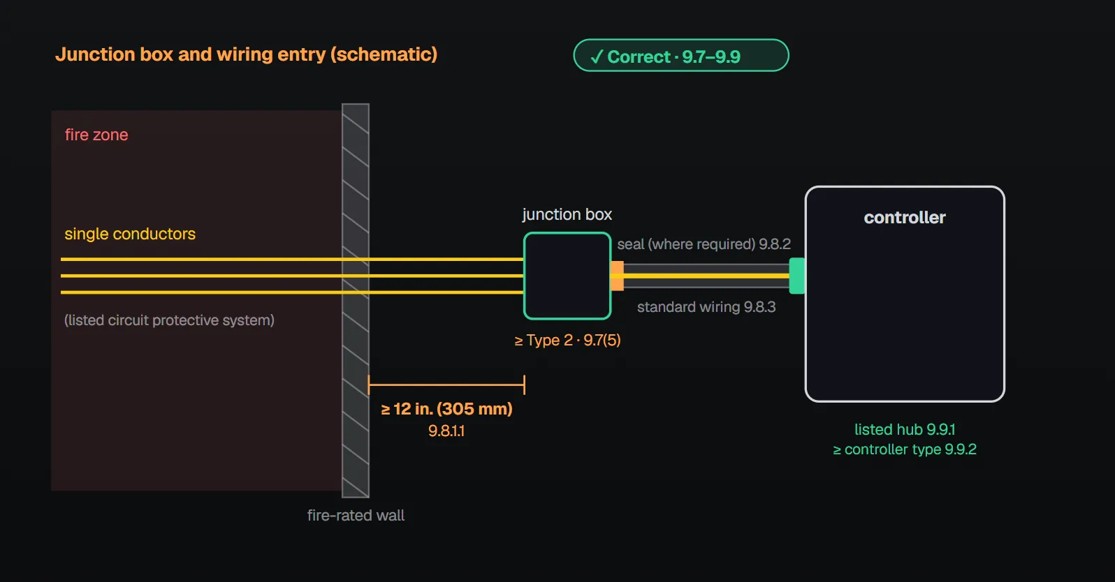
In short: the junction box is securely mounted; it does not violate the controller’s enclosure type rating or integrity or affect its short-circuit rating; it is at least a Type 2 dripproof enclosure listed to match the controller enclosure type; terminals and splices are listed (9.7). Neither the controller nor the transfer switch is used as a junction box to supply other equipment (including jockey pumps) or for splices (9.7(8), 9.7(9)). Single conductors terminate in a separate junction box installed ahead of the controller at least 12 in. (305 mm) beyond the fire-rated wall or floor bounding the fire zone, and do not enter the controller separately (9.8.1). Raceway terminates at the controller with listed conduit hubs whose type rating is at least that of the controller (9.9.1, 9.9.2).
Junction boxes (9.7)
Where fire pump wiring to or from a controller is routed through a junction box, the following are met (9.7):
| Requirement | Section |
|---|---|
| The junction box is securely mounted | 9.7(1) |
| Mounting does not violate the controller’s enclosure type rating (Annex A: see also 10.3.3) | 9.7(2) |
| Mounting does not violate the integrity of the controller | 9.7(3) |
| Mounting does not affect the short circuit rating of the controller | 9.7(4) |
| At least a Type 2, dripproof enclosure (junction box) is used | 9.7(5) |
| The enclosure is listed to match the controller enclosure type rating | 9.7(6) |
| Terminals, junction blocks and splices, where used, are listed | 9.7(7) |
| Neither the controller nor a power transfer switch is used as a junction box to supply other equipment, including jockey pumps (10.3.4.5.1, 10.3.4.6) | 9.7(8) |
| Neither the controller nor the transfer switch is used as a junction box for wire splices | 9.7(9) |
The NFPA 20 Handbook (2022) commentary explains why. If the box is mounted on the controller, an opening cut or drilled for it could let water in, expose live parts, or let flammable material escape during a short circuit; the enclosure must keep its strength to contain an internal fault. Where the box and controller share the same environment, the box needs an environmental rating at least equal to the controller enclosure; a more stringent rating is acceptable. Using the controller or transfer switch as a junction box brings other circuits’ conductors into the enclosure; an overcurrent on them could affect the controller, compromise its connections, or interfere with testing and maintenance. Where power is needed for loads such as a jockey pump, the Handbook notes it may be taken through a junction box, not from inside the controller; see also our jockey pump connection article.
Annex A.9.7(4) refers to 10.1.2.1 for the controller short circuit (withstand) rating.
Listed circuit protective system to controller (9.8)
- Where single (individual) conductors are used, they terminate in a separate junction box (9.8.1).
- The junction box is installed ahead of the controller, at least 12 in. (305 mm) beyond the fire-rated wall or floor bounding the fire zone (9.8.1.1).
- Single conductors do not enter the controller enclosure separately (9.8.1.2).
- Where required by the manufacturer of the listed electrical circuit protective system, by NFPA 70 or by the listing, the raceway between the junction box and controller is sealed at the junction box end per the manufacturer’s instructions (9.8.2).
- Standard wiring between the junction box and the controller is acceptable (9.8.3).
Why?
Per Annex A.9.8.1, cutting slots or rectangular cutouts in a controller violates the enclosure type rating and the short circuit (withstand) rating and voids the manufacturer’s warranty. Per Annex A.9.8.2, the seal prevents flammable gases from entering the controller.
According to the Handbook (2022) commentary, these single conductors are typically mineral insulated or similar fire-resistive cables; they are usually solid, while controller line terminals are rated for normal stranded building wire, hence the separate box. Conductors passing individually through steel sheet metal induce eddy currents that heat it, the Handbook says sometimes until it is red-hot; in a raceway the conductors’ fields largely cancel. Fire-resistive cables passing through a fire zone may give off flammable gases and smoke; the seal keeps these gases from reaching sparking parts such as contactors, relays or breakers. The Handbook adds that sealing compounds are specified by the system manufacturer and are those that do not degrade from gases or harden and become brittle with age.
Raceway terminations (9.9)
- Listed conduit hubs terminate raceway to the controller (9.9.1).
- The hub type rating is at least equal to that of the controller (9.9.2).
- The controller manufacturer’s installation instructions are followed (9.9.3).
- Alterations to the controller, other than conduit entry as allowed by NFPA 70, are approved by the AHJ (9.9.4).
Handbook (2022) commentary: if star nuts are used instead of hubs, water may enter the controller, especially through top entries; many controllers have been ruined this way. As controllers are at least Type 2, hubs are at least Type 2 listed; a Type 4 enclosure needs a Type 4 hub. Not following the manufacturer’s instructions may void the warranty and listing.
NFPA 70 correspondence
Per Annex D, Table D.1, these sections correspond to parts of NFPA 70 Article 695 (2023 edition): 9.8 → 695.6(H), 9.7 → 695.6(I), 9.9 → 695.6(J). Only the NFPA 20 text is given here.
Checklist
- Is the junction box secure, at least Type 2 and listed to match the controller enclosure type? (9.7(1), 9.7(5), 9.7(6))
- Does its mounting preserve the controller’s type rating, integrity and short circuit rating? (9.7(2)–9.7(4))
- Are terminals and splices listed? (9.7(7))
- Is nothing else fed from the controller or transfer switch, and are there no splices inside? (9.7(8), 9.7(9))
- Do single conductors terminate in a separate box at least 12 in. (305 mm) beyond the wall or floor? (9.8.1, 9.8.1.1)
- Is the raceway sealed at the box end where required? (9.8.2)
- Does the entry use a listed hub rated at least as the controller? (9.9.1, 9.9.2)
Frequently Asked Questions
Can a jockey pump be fed from the fire pump controller?
No. Neither the controller nor the transfer switch is used as a junction box to supply other equipment, including jockey pumps (9.7(8)); jockey pump supply conductors are not connected to the controller (10.3.4.6).
Can fire-resistive single conductors enter the controller directly?
No. Single conductors terminate in a separate junction box and do not enter the controller separately (9.8.1, 9.8.1.2). Per Annex A.9.8.1, cutting the controller enclosure violates its type rating and short circuit rating.
Where is that junction box located?
Ahead of the controller, at least 12 in. (305 mm) beyond the fire-rated wall or floor bounding the fire zone (9.8.1.1).
What enclosure rating does the junction box need?
At least Type 2 dripproof and listed to match the controller enclosure type rating (9.7(5), 9.7(6)). Its mounting must not violate the controller’s type rating, integrity or short circuit rating (9.7(2)–9.7(4)).
How is raceway connected to the controller?
With listed conduit hubs whose type rating is at least that of the controller (9.9.1, 9.9.2). Where required, the raceway between the junction box and controller is sealed at the box end (9.8.2).

SprinkCalc — Fire Sprinkler Design Across Three Standards
SprinkCalc covers hazard classification, design density and area, K-factor selection, water demand and hydraulic calculations for NFPA 13, FM Global and BS EN 12845 in a single iOS app, and exports a professional PDF report.
Download SprinkCalc on the App Store
MEP Calc — 110+ Engineering Calculators
MEP Calc bundles 110+ engineering modules in one iOS app: 21 fire calculations plus heating, cooling, HVAC, plumbing, steam and natural gas.
Download MEP Calc on the App StoreNFPA 20-2025, Standard for the Installation of Stationary Pumps for Fire Protection: 9.7(1)–9.7(9); 9.8.1, 9.8.1.1, 9.8.1.2, 9.8.2, 9.8.3; 9.9.1–9.9.4; 10.3.4.5.1, 10.3.4.6; Annex A.9.7(2), A.9.7(4), A.9.8.1, A.9.8.2 (explanatory); Annex D Table D.1 (informational). NFPA 20 Handbook 2022 commentary: 9.7(1)–9.7(3), 9.7(5), 9.7(8), 9.8.1, 9.8.2 and 9.9.1–9.9.3.