A fire on board is not a tank-farm fire: tanks sit almost side by side, outside help may be hours away, and the system must survive weather, vibration and salt water. NFPA 11-2024 covers ships in Chapter 11, which gives design information for low-expansion foam systems where the authority having jurisdiction requires them (11.1.1). Its first rule is easily missed: Chapters 4, 5, 7 and 9 do not apply to marine systems unless specifically referenced (11.1.2).
Chapter 11 sets its own numbers. Figures were read from page images of the 2024 edition; flag state, class and maritime rules are only named where NFPA 11 refers to them.
General requirements (11.1)
- Components: listed or approved for their purpose and approved for a marine environment; each manufacturer keeps a system design manual (11.1.3.1, 11.1.3.2).
- Concentrate: approved (11.1.4); for hydrocarbons by a test equivalent to the 9.3 m² (100 ft²) method in Annex F, with four consecutive fire tests, two in sea water and two in fresh water (11.1.4.1, 11.1.4.2). Polar solvent concentrate also needs approval by a method comparable to UL 162 (11.1.4.3).
- Supplies: foam per 4.3.2.2, water per 4.2.1.1 to 4.2.1.3 (11.1.5, 11.1.6).
- Time to actuate: the system must be capable of being actuated, with solution entering the foam main, within 3 minutes of notification of a fire (11.1.7).
Machinery spaces (11.2)
A fixed system in a machinery space must give at least 150 mm (6 in.) of foam over the largest area oil is expected to spread to (11.2.1). The rate follows the listing or AHJ approval (11.2.2) but is at least 6.5 L/min·m² (0.16 gpm/ft²) for at least 5 minutes (11.2.2.1).
- Foam suited to hydrocarbon fires reaches fixed outlets through permanent piping and control valves, with an expansion ratio of no more than 12:1 (11.2.3 to 11.2.5).
- Supply and proportioning may be shared with a deck system; concentrate covers the single largest demand (11.2.6, 11.2.7).
- Controls are simple and grouped where they can be reached in a fire, with permanent instructions and a local mechanical override on remote devices (11.2.8.1 to 11.2.8.3).
Tanker deck systems: purpose and control station (11.3.1 to 11.3.3)
11.3.1 expects the system to put out deck spill fires and hold a blanket while hot metal cools, control manifold fires (other than three-dimensional pressurised liquid fires) and tank fires over part of the cargo area, protect the crew while abandoning ship is arranged, and suppress vapour from an unignited spill. Explosions or collisions that spread fire beyond the area of the largest tank are outside its purpose.
The main control station is aft of the cargo area and stays operable with a fire in the protected area (11.3.2.1). Permanent diagrams and instructions show which valves to open and every step, each valve is labelled with its function, and the station has emergency lighting (11.3.2.2 to 11.3.2.3). With the deck system running, the fire main must still supply its required water streams (11.3.3).
Application rate and duration (11.3.4, 11.3.5)
The deck solution rate is the greatest of the hydrocarbon and polar solvent calculations (11.3.4). Hydrocarbon values follow the listing or AHJ approval but never fall below these minimums (11.3.4.1).
| Calculation | Hydrocarbons, minimum (11.3.4.1) | Polar solvents (11.3.4.2(3)) | Applied over |
|---|---|---|---|
| Deck spill | 6.5 L/min·m² (0.16 gpm/ft²) | Highest rate of any polar solvent the ship may carry | 10 percent of the cargo block deck area |
| Largest tank | 9.78 L/min·m² (0.24 gpm/ft²) | 150 percent of the highest rate | Horizontal sectional area of the single largest tank |
| Largest monitor | 3.0 L/min·m² (0.074 gpm/ft²), not less than 1250 L/min (330 gpm) | 45 percent of the highest rate, not less than 1250 L/min (330 gpm) | Area protected by the monitor, entirely forward of it |
The cargo block deck area is maximum breadth times the total length of the cargo tank spaces (11.3.4.1(1)). For polar solvents NFPA 11 gives no figure: solvents are grouped by fire test and the group rates are stated in the manufacturer’s design manual and approved; dedicated single-solvent tanks may be taken into account (11.3.4.2).
Concentrate covers 30 minutes (11.3.5.1), or 20 minutes for a ship carrying only hydrocarbons with inerted cargo vapour spaces (11.3.5.2). Pipe filling is added on top (11.3.5.3), and the duration is based on the actual capacity of the installed equipment (11.3.5.4).
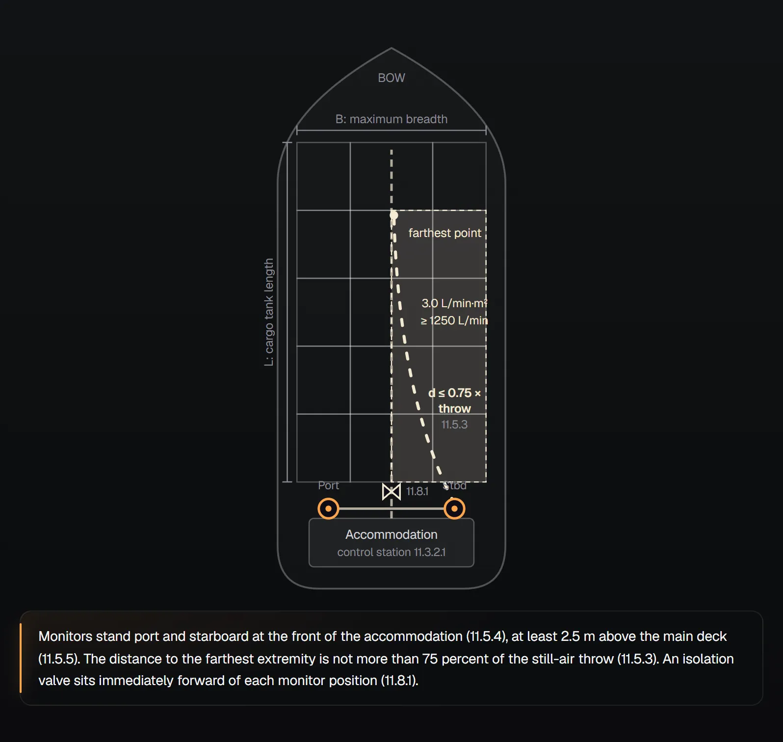
Worked example
Assumed: breadth 32 m, cargo tank length 180 m, largest tank 600 m², largest monitor area 1500 m², hydrocarbons only.
- Deck spill: 0.10 × 32 × 180 = 576 m²; 576 × 6.5 = 3744 L/min.
- Largest tank: 600 × 9.78 = 5868 L/min.
- Largest monitor: 1500 × 3.0 = 4500 L/min, above the 1250 L/min floor.
- Required rate: the greatest of the three, 5868 L/min (about 1550 gpm) (11.3.4).
- Monitor capacity: 50 percent of 5868 is 2934 L/min, the floor is 1250 L/min and the area rule gives 1500 × 3.02 = 4530 L/min. The largest, 4530 L/min, governs (11.5.1, 11.5.2).
- Solution: 5868 × 30 = 176,040 L over 30 minutes, plus the pipe-fill allowance (11.3.5.1, 11.3.5.3). The concentrate quantity is that solution volume times the concentrate’s listed proportioning rate.
11.3.4.1(3) prints 3.0 mm/min and 11.5.1 prints 3.02 mm/min; both convert 0.074 gpm/ft², and each clause’s own figure is used above.
Monitors and hand hoselines (11.4 to 11.6)
| Requirement | Value | Clause |
|---|---|---|
| Full application | 100 percent by one or two monitors immediately aft of the protected area | 11.4.1 |
| Tankers under 4000 t DWT | Hand hoselines only may replace monitors; each at least 25 percent of total solution flow | 11.4.2 |
| Monitor, area rule | At least 3.02 L/min·m² (0.074 gpm/ft²) over the deck area forward of it | 11.5.1 |
| Monitor, flow rule | At least 50 percent of the required rate and at least 1250 L/min (330 gpm) | 11.5.2 |
| Reach | Distance to the farthest extremity at most 75 percent of still-air throw | 11.5.3 |
| Position | Port and starboard at the front of the accommodation, facing the cargo deck | 11.5.4 |
| Height | At least 2.5 m (8.2 ft) above the main deck | 11.5.5 |
| Platform | Handrails or chain rails above 2 m (6.5 ft) | 11.5.6.7 |
| Large monitors | Over 3800 L/min (1000 gpm): two handholds or one handwheel per swivel | 11.5.7.1 |
| Hand hoseline | At least 380 L/min (100 gpm), still-air throw at least 15 m (50 ft) | 11.6.2 |
| Hose overlap | At least two hoselines on any part of the cargo block deck at once | 11.6.3 |
Foam must reach the whole cargo block deck, and bow or stern loading arrangements and the cargo line outside the block also get monitor cover (11.5.6 to 11.5.6.2). Monitors stand on platforms with 360° access by walkway or ladder, the isolation valve is reachable from the platform, and the monitor can be secured at sea and locked at full flow (11.5.6.3 to 11.5.7.3). Hoselines cover areas the monitors cannot see and sit on monitor platforms or at deck level (11.6.1, 11.6.4).
Hydraulic calculations (11.7)
NFPA 11 hands the method to NFPA 15 and treats foam solution as water (11.7.1). Concentrate lines follow the manufacturer’s design manual (11.7.2), and orifices may balance flow to monitors and outlets (11.7.3).
Valves, piping and freezing (11.8, 11.9, 11.13)
- Isolation valves sit in the water, concentrate and solution mains immediately forward of every monitor position, and each monitor and hose station has its own. They are operated from accessible places, fitted bonnet above horizontal and show their position at a glance (11.8.1 to 11.8.5).
- Hangers and supports are designed for marine service (11.9.2). Deck solution piping is independent of the fire main, with a check valve at any shared monitor (11.9.3, 11.9.4). Weather-exposed parts self-drain and wet parts are protected from freezing (11.9.5).
- Piping follows Section 4.7, but unprotected carbon steel is not used for solution piping, and solution piping built from unprotected steel is hot-dip galvanised after fabrication (11.13.1, 11.13.1.1, 11.13.6). Pipe exposed to fire is steel or a suitable alloy (11.13.2). Concentrate piping is compatible with the concentrate and is not galvanised (11.13.3, 11.13.4).
Concentrate storage and supply (11.11, 11.12)
The primary tank sits on or above the freeboard deck in the control station space, and all concentrate is stored where fire cannot cut it off and with no opening to the cargo area (11.11.1.1, 11.11.1.2). Tanks have an expansion dome, anti-slosh baffles, a corrosion-resistant pressure-vacuum vent and a sediment sump, with suction above the sump bottom (11.11.2.1 to 11.11.2.6). The space is heated against freezing (11.11.7.1); the label gives manufacturer, type and quantity, and only one concentrate type is carried (11.11.8, 11.11.9).
Proportioning is balanced pressure with a dedicated concentrate pump, though other types acceptable to the AHJ are permitted (11.12.1, 11.12.2). Pumps keep running if main power is lost (11.12.5). For motors and controllers NFPA 11 refers to IEEE 45, and for electric power to the SOLAS II-2 fire pump provisions (11.12.4, 11.12.6). Deck foam piping does not run through, beside or above the cargo pump room (11.12.8).
Testing and inspection (11.10)
11.10.1 ties inspection and testing to Chapters 11 and 12. Annual testing includes the 12.6 discharge tests (11.10.2), and the crew receives a video on use, inspection and testing (11.10.3). Acceptance tests are covered in NFPA 11 Acceptance Tests.
Design review questions. Greatest of the three deck calculations taken (11.3.4)? Each monitor meets the 50 percent, 1250 L/min and area rules (11.5.1, 11.5.2)? Farthest point within 75 percent of throw (11.5.3)? Pipe fill added to the supply (11.3.5.3)? Solution main independent of the fire main, check valve at shared monitors (11.9.3, 11.9.4)?
Tanks ashore: NFPA 11 Supplementary Hose Streams and Monitors, NFPA 11 Concentrate Supply and Proportioning and the NFPA 11 Design Criteria Calculator.
Frequently Asked Questions
How is the foam application rate for a tanker deck determined?
Three calculations are made and the greatest governs: 6.5 L/min·m² over 10 percent of the cargo block deck area, 9.78 L/min·m² over the sectional area of the largest tank, and 3.0 L/min·m² over the area protected by the largest monitor, with at least 1250 L/min. For polar solvents the same three are repeated with the approved rates from the manufacturer’s design manual (11.3.4, 11.3.4.1, 11.3.4.2).
How long must a ship’s deck foam system run?
Concentrate is provided for 30 minutes (11.3.5.1). A ship that carries only hydrocarbons and inerts its cargo vapour spaces may use 20 minutes (11.3.5.2). An allowance for filling the solution and concentrate piping is added (11.3.5.3).
What capacity does a tanker foam monitor need?
Each monitor delivers at least 50 percent of the required rate and at least 1250 L/min (330 gpm), and at least 3.02 L/min·m² over the deck area forward of it. The farthest extremity is no further than 75 percent of the still-air throw (11.5.1 to 11.5.3).
What does NFPA 11 require for machinery space foam systems?
A foam depth of at least 150 mm over the largest area oil can spread to, at least 6.5 L/min·m² for at least 5 minutes, and an expansion ratio no higher than 12:1. Controls are grouped where they can be reached in a fire, and remote devices have a local mechanical override (11.2.1 to 11.2.8.3).
Do NFPA 11’s land tank rules apply to ships?
No. Chapters 4, 5, 7 and 9 do not apply to marine systems unless specifically referenced (11.1.2). Chapter 11 sets its own rates and points back to particular clauses, such as 4.3.2.2, 4.6 or 4.7, where needed.

SprinkCalc — Fire Sprinkler Design Across Three Standards
SprinkCalc covers hazard classification, design density and area, K-factor selection, water demand and hydraulic calculations for NFPA 13, FM Global and BS EN 12845 in a single iOS app, and exports a professional PDF report.
Download SprinkCalc on the App Store
MEP Calc — 110+ Engineering Calculators
MEP Calc bundles 110+ engineering modules in one iOS app: 21 fire calculations plus heating, cooling, HVAC, plumbing, steam and natural gas.
Download MEP Calc on the App StoreNFPA 11, Standard for Low-, Medium-, and High-Expansion Foam, 2024 edition: 11.1 to 11.3.1 (p. 11-47); 11.3.1(1) to 11.4.2 (p. 11-48); 11.5 to 11.10.1 (p. 11-49); 11.10.2 to 11.13.7 (p. 11-50). No source other than NFPA 11 was used; NFPA 15, UL 162, IEEE 45 and SOLAS II-2 are named only as documents NFPA 11 refers to, and their content is not covered here. The plan and worked example use representative values prepared for this page. The binding text is the standard itself and the decision of the authority having jurisdiction.