The fuel tank decides how long a diesel-driven fire pump can run. NFPA 20-2025 Section 11.4 covers the tank and fuel piping, Section 11.5 the exhaust. Reasons are taken only from Annex A and the NFPA 20 Handbook (2022) commentary.
In short: the tank is sized for at least 12 hours of consumption (11.4.1.3.1), or 1 gal per hp (5.07 L per kW) when consumption is unknown (11.4.1.3.1.1), plus 5% expansion and 5% sump. Each engine has its own tank, limited to 1320 gal (4996 L), never below two-thirds full (11.4.1.2.2, 11.4.1.4.3, 11.6.4.1). The exhaust is independent and leaves the room (11.5).
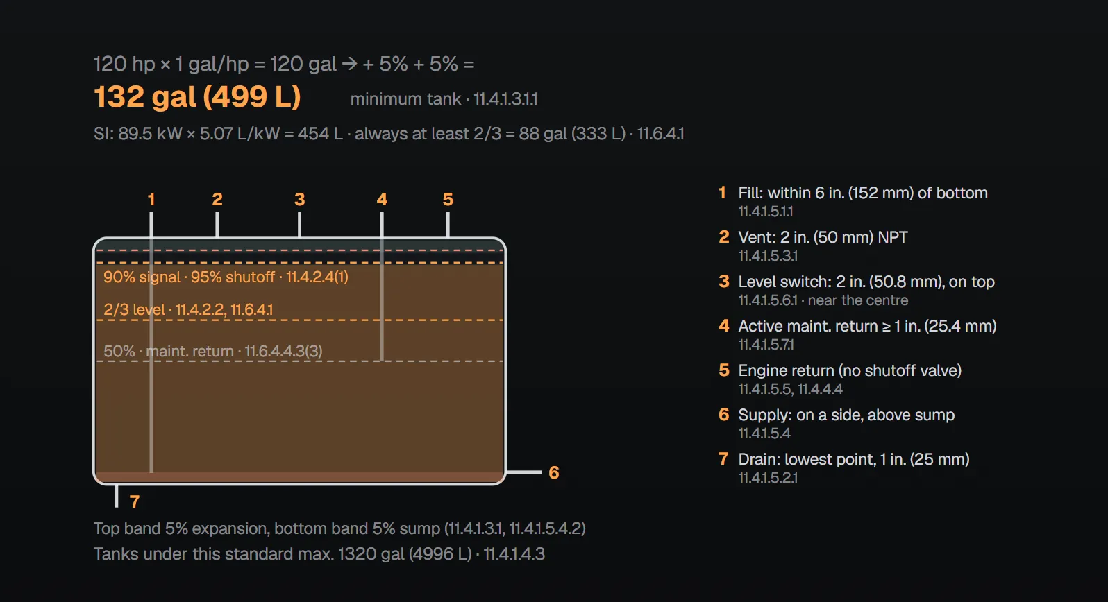
Capacity
| Case | Minimum capacity | Paragraph |
|---|---|---|
| Manufacturer’s published consumption data available | 12 hours of consumption + 5% expansion + 5% sump | 11.4.1.3.1 |
| Consumption not known | Engine power × 1 gal/hp (5.07 L/kW) + 5% + 5% | 11.4.1.3.1.1 |
| Larger tank | Decided case by case from conditions such as refill cycle and fuel heating due to recirculation | 11.4.1.3.2 |
| Upper limit | 1320 gal (4996 L); NFPA 37 applies above this | 11.4.1.4.3, 11.4.1.4.3.1 |
NFPA 20 Handbook (2022) example: a 120 hp (89.5 kW) engine needs 1 gal/hp × 120 hp = 120 gal (454 L); adding 5% + 5% gives a minimum tank of 132 gal (499.4 L). Annex A.11.4.1.3.1.1 says 1 gal per hp (5.07 L per kW) equals 1 pint per hp (0.634 L per kW) per hour for 8 hours, and recommends a reserve supply with transfer facilities where prompt replenishment is unlikely. The Handbook (2022) explains that 12 hours, together with refilling at two-thirds, secures 8 hours of engine run time.
Tank and connections
- Plans are submitted to the AHJ before the fuel system is installed (11.4.1.1). Tank and fuel serve only the fire pump engine; each engine has its own tank and its own supply and return lines (11.4.1.2).
- Tanks are single or double wall, built to a recognized standard such as UL 142 and mounted on noncombustible supports (11.4.1.4.1, 11.4.1.4.2). A single-wall tank sits within a wall, curb or dike holding its entire capacity (11.4.1.4.4). In a double-wall tank the interstitial space is monitored for leakage with a supervisory signal at the engine controller (11.4.1.5.8, 11.4.1.5.9).
| Connection | Rule | Paragraph |
|---|---|---|
| Fill | A fill pipe entering the top ends within 6 in. (152 mm) of the bottom; vibration minimized | 11.4.1.5.1.1 |
| Drain | 1 in. (25 mm) NPT at the lowest point; tank pitched to the drain | 11.4.1.5.2.1, 11.4.1.5.2.2 |
| Vent | 2 in. (50 mm) NPT or sized per UL 142; alternatively no smaller than the largest fill or withdrawal connection and at least 1¼ in. (32 mm) nominal ID | 11.4.1.5.3.1 |
| Engine supply | On a side of the tank; 5% of the volume stays as sump unusable by the engine; connection no smaller than the supply piping | 11.4.1.5.4.1–11.4.1.5.4.3 |
| Level switch | One 2 in. (50.8 mm) NPT port in the top, near the centre | 11.4.1.5.6.1 |
| Active fuel maintenance return | A minimum 1 in. (25.4 mm) NPT port in the top; plugged if no system is installed | 11.4.1.5.7.1, 11.4.1.5.7.2 |
Vent outlets discharge upward or horizontally away from walls, at least 5 ft (1.5 m) from building openings and at least 12 ft (3.7 m) above finished grade (11.4.1.6.1–11.4.1.6.3). Continuous level indication uses means other than sight tubes; an indicator activates at two-thirds and a low level starts a supervisory signal (11.4.2.1–11.4.2.3). Overfilling is prevented by an automatic device that signals the filler at 90% and shuts off at 95%, a permanent sign with a calibration chart at the fill point, or another approved procedure (11.4.2.4).
Location and fuel piping
- Tanks are above ground and not buried; where freezing [32 °F (0 °C)] is possible they are in the pump room (11.4.3.1, 11.4.3.2). Annex A.11.4.3 prefers the tank inside the pump room, where local rules allow, with fill and vent lines extended outdoors.
- The supply connection to the engine is no lower than the engine fuel transfer pump, and the maker’s static head limit is not exceeded with a full tank (11.4.3.3, 11.4.3.4).
- A flame-resistant flexible hose with a 30-minute rating equal to ISO 15540 and a pressure rating of at least twice the working pressure connects at the engine (11.4.4.1). Fuel piping is not galvanized steel or copper (11.4.4.2).
- No shutoff valve in the return line; a check valve only where the engine maker requires it (11.4.4.3.1, 11.4.4.4). The supply line has a manual valve locked open, and no other valve except as part of the listed engine (11.4.4.5).
Exhaust
| Topic | Rule | Paragraph |
|---|---|---|
| Independence and flexible connection | Independent exhaust for each engine; a stainless, seamless or welded corrugated (not interlocked) flexible section of at least 12 in. (305 mm) between engine outlet and pipe | 11.5.2.1, 11.5.2.2 |
| Size, insulation, support | No smaller than the engine outlet, short; insulated; supported independently of the flexible connection; back pressure within the maker’s recommendation | 11.5.2.3–11.5.2.5.1 |
| Combustibles | At least 9 in. (229 mm) clearance | 11.5.2.6 |
| Combustible roof | Ventilated metal thimble extending 9 in. (229 mm) above and below, at least 6 in. (152 mm) larger than the pipe | 11.5.2.7 |
| Combustible wall | Ventilated metal thimble at least 12 in. (305 mm) larger than the pipe, or a metal or burned clay thimble with at least 8 in. (203 mm) of insulation | 11.5.2.8 |
| Discharge point | A safe point outside the pump room, arranged to exclude water; not where it affects persons or endangers buildings; not toward combustibles or into flammable gases, vapors or dusts | 11.5.3.1–11.5.3.4 |
Exhaust after-treatment devices that could impair engine performance and reliability are not permitted; where the AHJ requires one, it is the active regeneration type with a pressure-limiting bypass (11.5.2.9, 11.5.2.10). Annex A.11.5.2 gives a conservative guideline: above 15 ft (4.5 m) of exhaust, increase the pipe one size for each added 5 ft (1.5 m).
Why?
- Separate tank: the Handbook (2022) says fuel in a tank can become contaminated and cause immediate engine failure; separate tanks eliminate that danger.
- Sump and supply height: per the Handbook (2022) the 5% sump holds sediment and condensation. With the supply no lower than the engine fuel pump the line stays under a small head, a leak shows, and drawing in air and losing prime is avoided. A tank too high can push fuel into the engine.
- No galvanized or copper: per the Handbook (2022) galvanized coating can scale and clog lines or injectors, and copper promotes microbiologically influenced corrosion (MIC).
- After-treatment: Annex A.11.5.2.9 notes that exhaust stays cool while the engine runs at pump shutoff during weekly tests, so a device can clog and fail to pass full-power exhaust in an emergency.
Mistakes named in the sources
- Feeding two engines from one tank, a valve in the return line, galvanized or copper piping (11.4.1.2.2, 11.4.4.4, 11.4.4.2). The Handbook (2022) ties the no-valve return to the engine’s need to return excess fuel to keep injection calibration.
- Ending the exhaust below a restaurant’s outdoor deck: the Handbook (2022) rejects it because the gases endanger people on the deck, a combustible deck needs hot gases directed away, and weekly runs make the problem ongoing.
Checklist
- Is capacity based on 12 hours of consumption or 1 gal/hp, plus 5% + 5%? (11.4.1.3)
- Is the tank at most 1320 gal (4996 L) and dedicated to one engine? (11.4.1.4.3, 11.4.1.2.2)
- Is fuel piping free of galvanized steel and copper, and the return line free of shutoff valves? (11.4.4)
- Is the exhaust independent, with a 12 in. (305 mm) flexible section, 9 in. (229 mm) from combustibles and discharging to a safe point? (11.5)
For room temperature and ventilation see the pump room article.
Frequently Asked Questions
How is a diesel fire pump fuel tank sized?
For at least 12 hours of run time from the manufacturer’s published consumption data, plus 5% expansion and 5% sump (NFPA 20-2025 11.4.1.3.1). If consumption is unknown, engine power × 1 gal per hp (5.07 L per kW), plus 5% + 5% (11.4.1.3.1.1).
What is the minimum tank for a 120 hp diesel engine?
Without consumption data, the Handbook (2022) example gives 120 gal + 10% = 132 gal (499.4 L). With the maker’s consumption data, use 12 hours of consumption + 5% + 5% (11.4.1.3.1).
How large can the fuel tank be?
Tanks used under NFPA 20 are limited to 1320 gal (4996 L) (11.4.1.4.3); larger tanks fall under NFPA 37 (11.4.1.4.3.1).
Can the fuel tank be outside the pump room?
The tank is above ground and not buried (11.4.3.1). Where freezing [32 °F (0 °C)] is possible it must be in the pump room (11.4.3.2). Annex A.11.4.3 prefers the tank inside the pump room where allowed, with fill and vent lines extended outdoors.
What dimensions apply to a diesel pump exhaust?
An independent exhaust per engine with a stainless flexible connection of at least 12 in. (305 mm) (11.5.2.1, 11.5.2.2) and at least 9 in. (229 mm) clearance to combustibles (11.5.2.6); thimble sizes for combustible roofs and walls are in 11.5.2.7 and 11.5.2.8. It discharges to a safe point outside the room (11.5.3.1).

SprinkCalc — Fire Sprinkler Design Across Three Standards
SprinkCalc covers hazard classification, design density and area, K-factor selection, water demand and hydraulic calculations for NFPA 13, FM Global and BS EN 12845 in a single iOS app, and exports a professional PDF report.
Download SprinkCalc on the App Store
MEP Calc — 110+ Engineering Calculators
MEP Calc bundles 110+ engineering modules in one iOS app: 21 fire calculations plus heating, cooling, HVAC, plumbing, steam and natural gas.
Download MEP Calc on the App StoreNFPA 20-2025, Standard for the Installation of Stationary Pumps for Fire Protection: 11.4.1.1–11.4.1.6.3; 11.4.2.1–11.4.2.4; 11.4.3.1–11.4.3.4; 11.4.4.1–11.4.4.5; 11.5.2.1–11.5.3.4; 11.6.4.1; Annex A.11.4.1.3.1.1, A.11.4.3, A.11.5.2, A.11.5.2.9 (explanatory). NFPA 20 Handbook 2022 commentary: Sections 11.4 and 11.5.