Inside an electric fire pump controller, power passes from the line to the motor through a voltage surge arrester, an isolating switch, a circuit breaker and the motor contactor, accompanied by locked rotor overcurrent protection and signal devices. NFPA 20-2025 Section 10.4 sets requirements for each. Controller location and enclosure (10.1–10.3) are covered in a separate article.
In short: a surge arrester is installed from each phase to ground, except in controllers above 600 V and controllers that withstand a 10 kV impulse or are listed to UL 1449 (10.4.1). The isolating switch and circuit breaker carry at least 115 percent of motor full-load current (10.4.2.3, 10.4.3.3.1(1)). The breaker uses nonthermal sensing, has an instantaneous trip setting of not more than 20 times full-load current, and does not trip on across-the-line starting (10.4.3.3.1, 10.4.3.3.1.1). The only other overcurrent device between the isolating switch and the motor is locked rotor protection: 8–12 seconds at locked rotor current, 3 minutes at a minimum of 300 percent of full-load current (10.4.4). Acceleration does not exceed 10 seconds (10.4.5.2.2). A silenceable signal actuates when motor current exceeds 120 percent in any phase for 12 seconds (10.4.6.4).
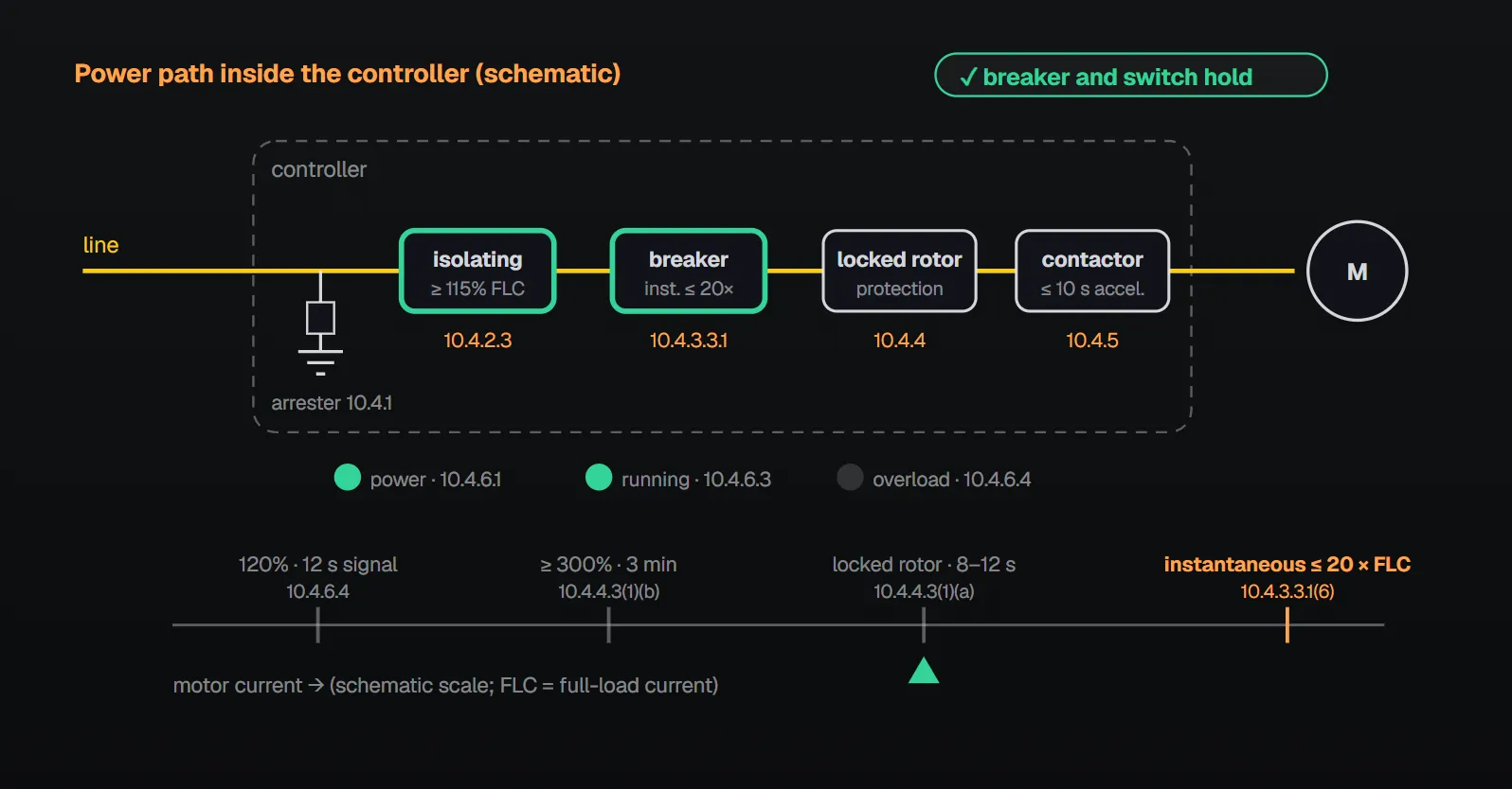
Rules, component by component
| Component | Rule | Section |
|---|---|---|
| Surge arrester | Complies with IEEE C62.1 or C62.11, from each phase to ground; rated to suppress surges above line voltage. Not required for controllers above 600 V, or where the controller withstands a 10 kV impulse per IEEE C62.41 without damage or is listed per UL 1449 | 10.4.1.1–10.4.1.4 |
| Isolating switch | Manually operable motor circuit switch or molded case switch with a horsepower rating not less than the motor; or a molded case switch rated at least 115 percent FLC and suitable for interrupting locked rotor current. Self-protecting instantaneous protection is permitted if it does not trip unless the breaker in the same controller trips. Externally operable; ampere rating at least 115 percent FLC | 10.4.2.1.1–10.4.2.3 |
| Labels and handle | Instruction label giving the order of operating the switch and breaker (may be part of the 10.3.7.3 label). Unless the switch meets 10.4.2.1.2 or is interlocked with the breaker, a warning not to open or close the switch while the breaker is closed. Without interlock, the handle has a spring latch needing the other hand | 10.4.2.4, 10.4.2.5 |
| Circuit breaker | Connected directly to the load side of the isolating switch, one pole per ungrounded conductor; externally operable, trips free of the handle, with a “Circuit breaker — disconnecting means” nameplate in letters at least 3/8 in. (10 mm) high | 10.4.3.1, 10.4.3.2 |
| Breaker electrical characteristics | Continuous rating at least 115 percent FLC; nonthermal sensing; instantaneous short-circuit protection; interrupting rating giving the suitability rating of 10.1.2.2; normal and emergency starting and running without tripping; instantaneous trip setting not more than 20 × FLC | 10.4.3.3.1 |
| Starting and restarting | Does not trip when starting a motor from rest across the line; does not trip when power is interrupted from a running pump or on a restart within less than 3 seconds (not applicable if a control circuit prevents restart within 3 seconds) | 10.4.3.3.1.1, 10.4.3.3.1.2 |
| Current limiters (integral to the breaker) | Only one rating accepted; hold 300 percent FLC for at least 30 minutes; do not open at locked rotor current; a spare set kept inside the controller | 10.4.3.3.2 |
| Locked rotor overcurrent protection | The only other overcurrent device required and permitted between the isolating switch and motor; located in the controller. For induction motors, time-delay type: 8–12 s at locked rotor current, 3 minutes at a minimum of 300 percent FLC. For dc motors, instantaneous, at least 400 percent FLC. Settings visibly indicated; resettable immediately with unchanged characteristics; trips by opening the breaker, which is external manual reset type | 10.4.4.1–10.4.4.3 |
| Motor contactor and starting | Horsepower rated, magnetic, a contact in each ungrounded conductor; running and starting contactors sized for locked rotor current. Timed automatic acceleration for reduced-voltage starting; acceleration not more than 10 s. Starting resistors allow one 5 s start every 80 s for at least 1 hour; reactors and autotransformers comply with UL 508 Table 113.1 | 10.4.5.1–10.4.5.5 |
| Operating coils | At 500 V or less, contactor coils supplied directly from the main power voltage, not through a transformer; above 500 V up to 600 V a transformer is permitted; dc coils may conditionally use the system dc supply | 10.4.5.6 |
| Single-phase sensors | May prevent starting under single phase; do not disconnect a running motor; sensor malfunction gives a local visible signal | 10.4.5.7 |
| Ground fault | No ground-fault protection that opens or disconnects the motor at currents below those needed to protect conductors; monitoring permitted if it does not trip the breaker | 10.4.5.8, 10.4.5.9 |
FLC: motor full-load current. Per 10.4.5.4.2, reactors and autotransformers over 200 hp may be designed to Part 3 of UL 508 Table 113.1 instead of Part 4.
Why?
- Annex A.10.4.1: operation of the surge arrester should not cause the isolating switch or breaker to open. Per the NFPA 20 Handbook (2022) commentary, the arrester keeps line surges from damaging controller components or making them inoperable.
- 115 percent: per the Handbook, the motor may draw 115 percent of full-load current because of its service factor (see 9.5.2.2(1)).
- Warning label: per the Handbook, only the breaker can manually close on and interrupt a short circuit; attempting it with the isolating switch could cause a fire or shock hazard.
- Nonthermal sensing: per the Handbook, thermal elements need cooling time before reset; the rule lets a breaker that trips during a fire be reset without waiting.
- No trip on full-voltage starting: per the Handbook, every controller has an emergency-run mechanical operator that starts the motor across the line regardless of starting type. Annex A.10.4.3.3.1.1 adds that the isolating switch must not trip either.
- 3 seconds: per the Handbook, the delay lets the motor’s back EMF decay so a normal start can be made.
- 8–12 s: per the Handbook, the aim is to keep starting torque applied long enough to break away a stuck or seized pump. Annex A.10.4.4.3(4): a device tripped by a locked rotor should not be reset more than two consecutive times without inspecting the motor for excessive heating and removing the cause.
- Annex A.10.4.5.8: modules that trip on low-level ground or leakage currents are not permitted because they could trip during an emergency; the motor and circuit can generally tolerate low ground current without damage.
Signals on the controller (10.4.6)
- A power available indicator monitors all phases at the line terminals of the motor contactor (or bypass contactor); a pilot lamp is accessible for replacement (10.4.6.1.1, 10.4.6.1.2).
- Phase reversal is shown by a visible indicator (10.4.6.2.1); per the Handbook, a reversed pump runs backward, delivers very limited water and is damaged if run for long.
- A visual indicator actuates whenever the controller is in a motor-running condition (10.4.6.3).
- A silenceable visual and audible signal actuates when motor current exceeds 120 percent of full-load amperes in any phase for 12 seconds (10.4.6.4).
- With multiple power sources, phase loss and phase reversal may be monitored upstream of the contactor line terminals, provided all sources are monitored (10.4.6.1.3, 10.4.6.2.2).
Remote alarms and contacts (10.4.7, 10.4.8)
Where the pump room is not constantly attended, audible or visible signals powered by a separate reliable supervised source not exceeding 125 V are provided at a point of constant attendance (10.4.7.1). They indicate (10.4.7.2):
| Signal | Section |
|---|---|
| Pump or motor running | 10.4.7.2.1 |
| Loss of phase (all phases monitored, running or at rest) | 10.4.7.2.2 |
| Phase reversal | 10.4.7.2.3 |
| Controller connected to alternate source (where two sources meet 9.3.2) | 10.4.7.2.4 |
| Alternate source isolating switch or circuit breaker open or tripped | 10.4.7.2.5 |
| Controller or system trouble: ground-fault signal (where provided), pressure-sensing device signals, variable-speed trouble, fail to start, motor overload, single phase, pressures above rated components, low reservoir level, lowest permissible suction pressure | 10.4.7.2.6 |
Controllers have contacts for remote indication of 10.4.7.2.1 through 10.4.7.2.3 and 10.4.7.2.6, and, with a transfer switch, of 10.4.7.2.4 and 10.4.7.2.5 (10.4.8). Per Annex A.10.4.7, to supervise the power source of the alarm circuit, the controller can be arranged to start upon failure of the supervised alarm circuit power.
Checklist
- Is a surge arrester installed, or is the 10.4.1.3 / 10.4.1.4 exception documented?
- Are the isolating switch and breaker at least 115 percent FLC, and the instantaneous trip not more than 20 × FLC? (10.4.2.3, 10.4.3.3.1)
- Are the warning or instruction label and the breaker nameplate in place? (10.4.2.4, 10.4.3.2(3))
- Is locked rotor protection set to 8–12 s at locked rotor current and 3 minutes at a minimum of 300 percent FLC, with visible settings? (10.4.4.3)
- Is there no ground-fault protection that trips the motor at low current? (10.4.5.8)
- Are remote alarms powered from a supervised source of not more than 125 V at a constantly attended point? (10.4.7.1)
Frequently Asked Questions
How is the fire pump circuit breaker rated?
Continuous rating at least 115 percent of motor full-load current and an instantaneous trip setting of not more than 20 times; it uses nonthermal sensing and does not trip on across-the-line starting (10.4.3.3.1, 10.4.3.3.1.1).
When does locked rotor protection trip?
For induction motors, 8–12 seconds at locked rotor current and 3 minutes at a minimum of 300 percent of full-load current; it trips by opening the breaker and can be reset immediately (10.4.4.3). Annex A.10.4.4.3(4) recommends no more than two consecutive resets without inspecting the motor.
Can the controller have ground-fault protection?
Not protection that opens or disconnects the motor at currents below those needed to protect conductors (10.4.5.8); ground-fault monitoring is permitted if it does not trip the breaker (10.4.5.9).
Is a surge arrester always required?
From each phase to ground, except in controllers above 600 V and where the controller withstands a 10 kV impulse per IEEE C62.41 without damage or is listed per UL 1449 (10.4.1.1–10.4.1.4).
When is the motor overload signal given?
A silenceable visual and audible signal actuates when motor current exceeds 120 percent of full-load amperes in any phase for 12 seconds (10.4.6.4); motor overload is also part of the remote controller or system trouble signal (10.4.7.2.6).

SprinkCalc — Fire Sprinkler Design Across Three Standards
SprinkCalc covers hazard classification, design density and area, K-factor selection, water demand and hydraulic calculations for NFPA 13, FM Global and BS EN 12845 in a single iOS app, and exports a professional PDF report.
Download SprinkCalc on the App Store
MEP Calc — 110+ Engineering Calculators
MEP Calc bundles 110+ engineering modules in one iOS app: 21 fire calculations plus heating, cooling, HVAC, plumbing, steam and natural gas.
Download MEP Calc on the App StoreNFPA 20-2025, Standard for the Installation of Stationary Pumps for Fire Protection: 10.4.1.1–10.4.1.4; 10.4.2.1.1–10.4.2.5.2; 10.4.3.1–10.4.3.3.2; 10.4.4.1–10.4.4.3; 10.4.5.1–10.4.5.9; 10.4.6.1.1–10.4.6.4; 10.4.7.1–10.4.7.2.6; 10.4.8; Annex A.10.4.1, A.10.4.3.3.1.1, A.10.4.4.3(4), A.10.4.5.8, A.10.4.7 (explanatory). NFPA 20 Handbook 2022 commentary: 10.4.1.1, 10.4.2.3, 10.4.2.4, 10.4.3.3.1(2), 10.4.3.3.1.1, 10.4.3.3.1.2, 10.4.4.3(1)(a) and 10.4.6.2.1.