The controller of an electric fire pump starts, protects and reports on the motor. The first three parts of NFPA 20-2025 Chapter 10 cover its listing and marking (10.1), where it goes (10.2) and how it is built (10.3). Internal components (10.4) and starting and stopping (10.5) are separate topics; for a general overview see our fire pump controller article.
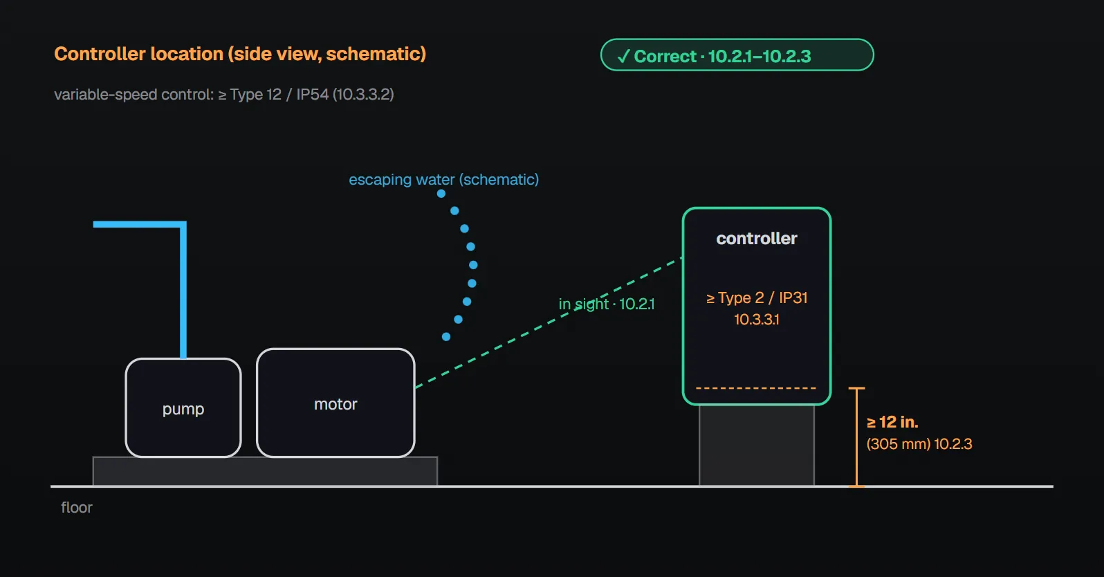
In short: controllers and transfer switches are specifically listed for electric motor-driven fire pump service, suitable for the available short-circuit current at their line terminals, and fully assembled and tested at the factory (10.1.2.1–10.1.2.3). The controller is fully functional within 10 seconds of ac power (10.1.2.7) and has arc flash mitigation, either a separately enclosed isolating switch or an arc-resistant listing (10.1.4). It is as close as practical to, and within sight of, the motor (10.2.1), protected from water escaping from the pump (10.2.2), with current-carrying parts at least 12 in. (305 mm) above the floor (10.2.3). The enclosure is at least NEMA Type 2 or IP31; with variable-speed control at least NEMA Type 12 or IP54 (10.3.3.1, 10.3.3.2). The controller is not a junction box, and jockey pump conductors are not connected to it (10.3.4.5.1, 10.3.4.6).
Listing, marking and readiness (10.1)
- All controllers and transfer switches are specifically listed for electric motor-driven fire pump service (10.1.2.1).
- The controller and transfer switch are suitable for the available short-circuit current at their line terminals and marked accordingly (“not more than … amperes RMS symmetrical at … volts ac” or equivalent) (10.1.2.2.1, 10.1.2.2.2).
- Controllers are completely assembled, wired and tested by the manufacturer before shipment, including those shipped in sections; these are reassembled in the field and the assembly is verified by the manufacturer or its representative (10.1.2.3, 10.1.2.3.1, 10.1.2.3.2).
- Controllers are marked “Electric Fire Pump Controller” and show the manufacturer’s name, identifying designation, maximum rated pressure, enclosure type designation and complete electrical rating (10.1.2.5.1). Where multiple pumps serve different areas, each controller carries a sign showing the area served (10.1.2.5.2).
- The controller is fully functional within 10 seconds of applying ac power (10.1.2.7).
- All electrical control equipment design complies with NFPA 70 Article 695 and other applicable documents (10.1.3).
- For arc flash mitigation, either the isolating switch with instantaneous-only overcurrent protection is in a separate enclosure or compartment attached to the controller, able to totally isolate incoming normal power from the main enclosure and marked to prohibit energized work, or the controller is listed as arc resistant (10.1.4, 10.1.4.1.1, 10.1.4.1.2, 10.1.4.2).
Per Annex A.10.1.2.2, “suitable for use” means the controller and transfer switch have shown short-circuit withstandability and interrupting capacity at the stated current by prototype tests. A short-circuit study should establish the available current at the controller; after a high fault current the controller and transfer switch might not be suitable for further use without inspection or repair. The NFPA 20 Handbook (2022) commentary says an installation is unsafe where the available short-circuit current exceeds the marked rating.
Controller location (10.2)
| Rule | Section | Annex A / Handbook (2022) reason |
|---|---|---|
| As close as practical to the motor it controls and within sight of it | 10.2.1 | Viewing the pump and motor before starting matters for personnel safety and to see nothing blocks the pump; proximity minimizes voltage drop. If the controller must be outside the pump room, a glazed opening should allow observing the motor and pump, and the pressure control line should be protected against freezing and mechanical injury (A.10.2.1). |
| Located or protected so it is not damaged by water escaping from the pump or its connections | 10.2.2 | A Type 2 enclosure only protects against water dripping from above; valve spray patterns and possible leak points should be determined. |
| Current-carrying parts at least 12 in. (305 mm) above the floor | 10.2.3 | To keep water out of the circuitry. The Handbook also mentions a 4 in. (100 mm) housekeeping pad or equivalent as good practice. |
| Working clearances comply with NFPA 70 Article 110 | 10.2.4 | — |
Construction (10.3)
Enclosure and mounting
- All equipment is suitable for locations with a moderate degree of moisture, such as a damp basement (10.3.1), and is mounted substantially on a single noncombustible supporting structure (10.3.2).
- The enclosure is at least NEMA Type 2 dripproof or IP31 (10.3.3.1). Controllers with variable-speed pressure-limiting or suction-limiting control are at least NEMA Type 12 dusttight or IP54 (10.3.3.2).
- Outdoors or in special environments, enclosures rated for that environment are used (10.3.3.3); per Annex A.10.3.3.3, NEMA 3R (IP-34) or NEMA 4 (IP-66) would typically be used outdoors.
- The enclosure is grounded per NFPA 70 Article 250 (10.3.3.4).
Connections and wiring
- Means on the exterior read all line currents and line voltages within ±2 percent of motor nameplate values (10.3.4.3); where a self-regulating variable speed fire pump unit is on the controller output, its meters are used instead (10.3.4.3.1).
- The controller is not used as a raceway or junction box for any purpose, including supplying other equipment, splicing wires or connecting external surge suppression (10.3.4.5.1).
- No undervoltage, phase loss, frequency sensitive or other device that prohibits electrical actuation of the motor contactor is field installed (10.3.4.5.2).
- Except as provided in 4.21.2.2(1), 10.5.2.8.4 and 10.9.4, lockout, remote shutdown or interlock preventing normal operation is not permitted unless approved by the AHJ (10.3.4.5.3).
- Jockey pump supply conductors are not connected to the controller (10.3.4.6).
- Circuits necessary for proper controller operation have no overcurrent protective devices (10.3.5.1); the transformer secondary and control circuitry may be ungrounded except as required in 10.6.5.4 (10.3.5.2).
- All switching equipment for manually connecting, disconnecting, starting or stopping the motor is externally operable (10.3.6).
Handbook (2022) reasons: the ±2 percent accuracy replaced 5 percent in the 2019 edition; exterior reading removes the need to reach into energized circuits and the shock and arc flash exposure that came with it. 10.3.4.5.2 and 10.3.5.1 keep the number of items in the pump’s critical path low; a wrong-size replacement fuse or a manually tripped device could cut off fire water. Remote shutdown is undesirable because a fire may not be detectable from a remote location. Annex A.10.3.4.5.3 gives criteria for interlocking a redundant pump not required for fire protection (for example, the redundant pump starts if the required pump fails to start, and manual operation is not affected).
Diagrams, instructions and marking
| Document | Where | Section |
|---|---|---|
| Electrical schematic diagram | Permanently attached inside the controller enclosure | 10.3.7.1 |
| Field wiring terminals marked to match the field connection diagram | At the terminals | 10.3.7.2 |
| Basic emergency operating instructions: opening and closing sequence of normal and emergency isolating switches (if separate from the breaker) and circuit breakers, emergency-run mechanical control, manual electrical start and stop | On the exterior of the controller | 10.3.7.3.1 |
| Installation instructions: mounting holes, conduit entrance locations, plumbing connection, power and remote alarm/control lug sizes, external connection drawing | With the controller, without requiring a website or other electronic means | 10.3.7.3.2 |
| Advanced operating instructions: model and options, specifications, menu functions, settings, maintenance | With the controller or, at the manufacturer’s option, electronically | 10.3.7.3.3 |
The controller manufacturer’s installation instructions are followed (10.3.7.4). Each motor control device, switch and circuit breaker is marked with the manufacturer, identifying number and electrical rating, visible after installation (10.3.8.1, 10.3.8.2). Handbook: basic instructions are on the exterior because electronic documentation may not be at hand in an emergency.
Checklist
- Is the controller listed for fire pump service with a short-circuit rating suitable for the available current? (10.1.2.1, 10.1.2.2.1)
- Is arc flash mitigation provided: a separately enclosed isolating switch or an arc-resistant listing? (10.1.4)
- Is the controller within sight of the motor, protected from water, with live parts at least 12 in. (305 mm) above the floor? (10.2.1–10.2.3)
- Is the enclosure at least Type 2 / IP31, or Type 12 / IP54 with variable speed? (10.3.3.1, 10.3.3.2)
- Is the controller free of junction box use and jockey pump connections? (10.3.4.5.1, 10.3.4.6)
- Are the basic operating instructions on the exterior? (10.3.7.3.1)
Frequently Asked Questions
Can the controller be outside the pump room?
The controller is as close as practical to and within sight of the motor (10.2.1). Per Annex A.10.2.1, if it must be outside the pump room, a glazed opening should allow observing the motor and pump, and the pressure control line should be protected against freezing and mechanical injury.
How high above the floor must the controller be?
Its current-carrying parts are at least 12 in. (305 mm) above the floor (10.2.3). The Handbook (2022) mentions a 4 in. (100 mm) housekeeping pad as good practice.
What enclosure rating is required?
At least NEMA Type 2 or IP31 (10.3.3.1); controllers with variable-speed pressure- or suction-limiting control at least NEMA Type 12 or IP54 (10.3.3.2). Outdoors and in special environments, a suitably rated enclosure (10.3.3.3).
How soon after power-up must the controller be ready?
Fully functional within 10 seconds of applying ac power (10.1.2.7).
Can a phase-failure relay or remote shutdown be added to the controller?
No undervoltage, phase loss, frequency sensitive or other device that prohibits electrical actuation of the motor contactor is field installed (10.3.4.5.2). Lockout, remote shutdown or interlock preventing normal operation is not permitted without AHJ approval, except as provided in 4.21.2.2(1), 10.5.2.8.4 and 10.9.4 (10.3.4.5.3).

SprinkCalc — Fire Sprinkler Design Across Three Standards
SprinkCalc covers hazard classification, design density and area, K-factor selection, water demand and hydraulic calculations for NFPA 13, FM Global and BS EN 12845 in a single iOS app, and exports a professional PDF report.
Download SprinkCalc on the App Store
MEP Calc — 110+ Engineering Calculators
MEP Calc bundles 110+ engineering modules in one iOS app: 21 fire calculations plus heating, cooling, HVAC, plumbing, steam and natural gas.
Download MEP Calc on the App StoreNFPA 20-2025, Standard for the Installation of Stationary Pumps for Fire Protection: 10.1.2.1–10.1.2.3.2, 10.1.2.5.1, 10.1.2.5.2, 10.1.2.7; 10.1.3; 10.1.4, 10.1.4.1.1, 10.1.4.1.2, 10.1.4.2; 10.2.1–10.2.4; 10.3.1–10.3.3.4; 10.3.4.3–10.3.8.2; Annex A.10.1.2.2, A.10.2.1, A.10.3.3.3, A.10.3.4.5.3 (explanatory). NFPA 20 Handbook 2022 commentary: 10.1.2.2.1, 10.1.4, 10.2.1–10.2.3, 10.3.4.3, 10.3.4.5.2, 10.3.4.5.3, 10.3.5.1 and 10.3.7.3.1.