A fire pump unit is made up of the pump, driver and controller, and NFPA 20-2025 ties the three together with rules. Section 4.7 sets out which pump counts as a fire pump, which drivers may be used, how pumps, drivers and controllers are paired, how the driver is sized, and the maximum pressure of a centrifugal pump. This article summarizes those rules and their reasons from Annex A and the NFPA 20 Handbook (2022) commentary.
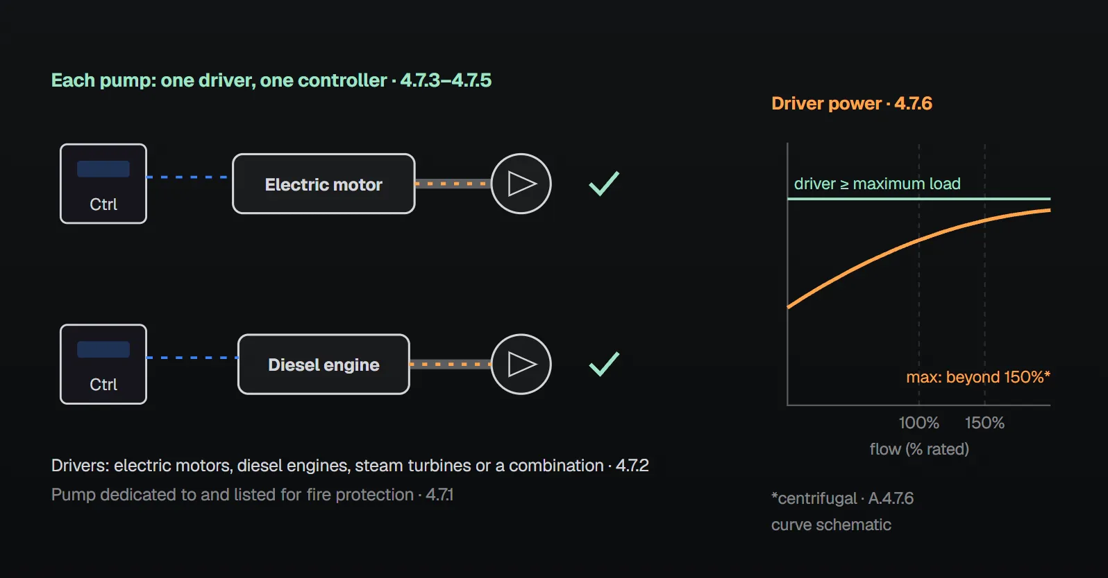
In short: fire pumps are dedicated to and listed for fire protection service (4.7.1). Acceptable drivers at a single installation are electric motors, diesel engines, steam turbines or a combination (4.7.2). A pump has no more than one driver (4.7.3); each fire pump has its own dedicated driver unless 8.6.3.1 permits otherwise (4.7.4); each driver or water mist positive displacement pumping unit has its own dedicated controller (4.7.5). The driver provides the power to run the pump at rated speed and maximum pump load under any flow condition (4.7.6).
Dedicated and listed pump
Fire pumps are dedicated to and listed for fire protection service (4.7.1). Listed means included in a list published by an organization acceptable to the AHJ that maintains periodic inspection of production, and whose listing states that the equipment meets designated standards or has been tested and found suitable for a specified purpose (3.2.3).
Annex A.4.7.1 marks the limits of this rule: it does not preclude pumps in public and private water supplies that provide water for domestic, process and fire protection purposes. Such pumps are not fire pumps and are not expected to meet all requirements of the standard; they are permitted for fire protection if considered reliable by the analysis required in Section 4.6. The reliability evaluation should include at least the levels of supervision and rapid response typical of municipal water systems. A campus that needs a fire protection pump typically installs a dedicated fire pump, per this standard, in parallel with a domestic pump or on a dedicated fire branch or loop off the water supply.
The NFPA 20 Handbook (2022) commentary warns about parallel arrangements: on a combined fire/domestic distribution system, domestic pumps should operate at or close to the fire pump pressures. Operating one or two fire protection devices might not lower the system pressure enough to start the fire pump, and domestic pumps running well below the fire pump discharge pressure might not provide adequate pressure for the initial demand.
Driver type and number
| Rule | Clause | Note or exception |
|---|---|---|
| Drivers at a single installation: electric motors, diesel engines, steam turbines or a combination | 4.7.2 | Selection clauses 9.5.2, 11.2.2 and 13.1.2 (4.7.6) |
| A pump has no more than one driver | 4.7.3 | A.4.7.3: dual-driver installations made before adoption of the 1974 edition need not be replaced |
| Each fire pump has its own dedicated driver | 4.7.4 | 8.6.3.1: a single driver may drive more than one positive displacement pump; 8.6.3.2: redundant pump systems may not share a common driver |
| Each driver or water mist positive displacement pumping unit has its own dedicated controller | 4.7.5 | Handbook: the pumps in the unit work together, so one controller per unit |
According to the Handbook (2022) commentary on 4.7.4, pumps in a water mist positive displacement pumping unit may share a common driver because they are listed and operate as a unit, with multiple low-volume pumps supplying the same system in parallel. The standard defines the controller as a group of devices that govern the starting and stopping of the driver in a predetermined manner and monitor and signal the status of the unit (3.3.24). More: fire pump controller (NFPA 20).
Driver power: sized for maximum load
The driver is selected per 9.5.2 for electric motors, 11.2.2 for diesel engines or 13.1.2 for steam turbines, to provide the power to operate the pump at rated speed and maximum pump load under any flow condition (4.7.6). Annex A.4.7.6 explains why:
- For centrifugal and turbine pumps, the maximum brake horsepower typically occurs at a flow beyond 150% of rated capacity.
- For positive displacement pumps, maximum brake horsepower typically occurs when the relief valve is flowing 100% of rated pump capacity.
- A pump on a variable speed driver can run slower, but the driver is still selected for the power needed at rated speed and maximum load under any flow condition.
Handbook (2022): the maximum power is read from a pump curve; the certified curve exists only once the pump is built, but a generic curve from the manufacturer gives the maximum horsepower demand in advance. Curve: fire pump curve: churn and 150%.
Maximum pressure and variable speed
Net shutoff (churn) pressure plus the maximum static suction pressure, adjusted for elevation, does not exceed the component pressure rating (4.7.7.1); pressure relief valves and pressure-regulating devices may not be used to meet this (4.7.7.2). Annex A.4.7.7.2 does not restrict pressure-reducing valves downstream of the discharge isolation valve. Variable speed pumps as defined in the standard are acceptable for limiting system pressure (4.7.7.3.1); set pressure plus the maximum pressure variance during variable speed operation, adjusted for elevation, does not exceed the rating of any component (4.7.7.3.2). Annex A.4.7.7.3.2 says this accounts for the set pressure tolerance stated by the manufacturer.
Handbook (2022) example: a standpipe system demanding 1000 gpm (3785 L/min) at 150 psi (10.3 bar) needs a pump rated 1000 gpm at 160 psi (11 bar), assuming 0 psi at the suction flange. That pump can produce as much as 224 psi (15.5 bar), well above the 175 psi (12.1 bar) component rating. A variable speed pump set at 165 psi (11.4 bar) prevents overpressurization while meeting the demand. Relief valve location and limits: fire pump main relief valve location; variable speed units: self-regulating variable speed fire pump.
Common field errors and the reason in the sources
| Error | Rule | Reason given in the sources |
|---|---|---|
| Treating a domestic or process pump as a fire pump | 4.7.1 | A.4.7.1: it is not a fire pump; usable only if found reliable by the Section 4.6 analysis |
| Running a parallel domestic pump well below fire pump pressure | 4.7.1 commentary | Handbook: the fire pump may not start and initial demand may lack pressure |
| Two drivers on one pump | 4.7.3 | No reason given; A.4.7.3 exempts only pre-1974 installations |
| Two drivers on one controller | 4.7.5 | No reason given; the only exception is a water mist positive displacement unit |
| Redundant positive displacement pumps on one driver | 8.6.3.2 | No reason given |
| Sizing the driver for rated-point power | 4.7.6 | A.4.7.6: maximum brake horsepower typically occurs beyond 150% flow |
| Trimming excess churn pressure with a relief valve or regulating device | 4.7.7.2 | A.4.7.7: not an acceptable method under normal operating conditions |
Checklist
- Is the pump dedicated to and listed for fire protection service (4.7.1)?
- One driver per pump and a separate controller per driver (4.7.3–4.7.5)?
- Is any common driver within 8.6.3.1, with redundant pumps kept separate (8.6.3.1, 8.6.3.2)?
- Does driver power cover maximum load at rated speed and any flow (4.7.6, A.4.7.6)?
- Is net churn plus maximum static suction below the component rating; for variable speed, set pressure plus variance checked (4.7.7.1, 4.7.7.3.2)?
Frequently Asked Questions
Can a domestic water pump serve as a fire pump?
Fire pumps are dedicated to and listed for fire protection service (4.7.1). Per Annex A.4.7.1, utility pumps supplying domestic, process and fire water are not fire pumps; they may be used for fire protection if considered reliable by the Section 4.6 analysis.
Can one fire pump have both an electric motor and a diesel engine?
No. A pump shall not be equipped with more than one driver (4.7.3). Annex A.4.7.3 only exempts dual-driver installations made before the 1974 edition. Separate electric and diesel pumps may exist at the same installation (4.7.2).
Can two pumps share one controller?
Each driver or water mist positive displacement pumping unit has its own dedicated controller (4.7.5). A single controller is accepted only for a water mist positive displacement pumping unit listed as a unit.
What power is a fire pump driver sized for?
For running the pump at rated speed and maximum pump load under any flow condition (4.7.6). Annex A.4.7.6: maximum brake horsepower typically occurs beyond 150% of rated flow for centrifugal and turbine pumps, and with the relief valve flowing 100% of rated capacity for positive displacement pumps.
How is high churn pressure limited?
Net churn plus maximum static suction pressure must not exceed the component rating (4.7.7.1), and relief valves or pressure-regulating devices may not be used to meet this (4.7.7.2). Variable speed pumps as defined in the standard are acceptable; set pressure plus maximum variance must not exceed any component rating (4.7.7.3.1, 4.7.7.3.2).

SprinkCalc — Fire Sprinkler Design Across Three Standards
SprinkCalc covers hazard classification, design density and area, K-factor selection, water demand and hydraulic calculations for NFPA 13, FM Global and BS EN 12845 in a single iOS app, and exports a professional PDF report.
Download SprinkCalc on the App Store
MEP Calc — 110+ Engineering Calculators
MEP Calc bundles 110+ engineering modules in one iOS app: 21 fire calculations plus heating, cooling, HVAC, plumbing, steam and natural gas.
Download MEP Calc on the App StoreNFPA 20-2025, Standard for the Installation of Stationary Pumps for Fire Protection: 3.2.3, 3.3.24; 4.7.1–4.7.6; 4.7.7.1, 4.7.7.2, 4.7.7.3.1, 4.7.7.3.2; 8.6.3.1, 8.6.3.2; Annex A.4.7.1, A.4.7.3, A.4.7.6, A.4.7.7, A.4.7.7.2, A.4.7.7.3.2 (explanatory). NFPA 20 Handbook 2022 commentary: parallel domestic pump commentary after A.4.7.1; 4.7.4, 4.7.5 and 4.7.6 commentary; 4.7.7.3.1 example.