A pump and driver aligned at the factory do not stay aligned on their way to site. NFPA 20-2025 6.4 and 6.5 state briefly how a centrifugal fire pump is mounted on its base plate and foundation and connected to its driver; Annex A.6.5 walks through coupling alignment step by step.
In short: overhung-impeller and impeller-between-bearings pumps and their driver are mounted on a common grouted base plate in accordance with the manufacturer’s instructions (6.4.1). The base plate is securely attached to a solid foundation so that shaft alignment is ensured and is set level; the foundation forms a permanent and rigid support (6.4.3–6.4.5). Separately coupled pumps with electric motor or diesel engine drivers are connected by a flexible coupling or flexible connecting shaft, listed for fire pump service and installed per the listing (6.5.1.1, 6.5.1.2). Alignment follows the coupling and pump manufacturers’ specifications and ANSI/HI 1.4 (6.5.2).
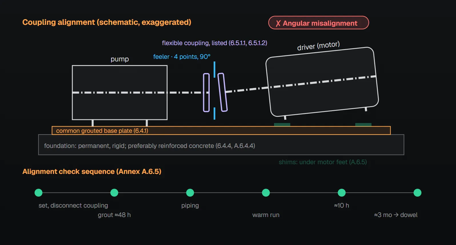
Foundation and setting (6.4)
| Rule | Section |
|---|---|
| Overhung-impeller and impeller-between-bearings pumps and driver are mounted on a common grouted base plate in accordance with the manufacturer’s instructions | 6.4.1 |
| Overhung impeller close coupled in-line pumps (Figure A.6.1.1(c)) may be mounted on a base attached to the pump mounting base plate | 6.4.2 |
| The base plate is securely attached to a solid foundation so that pump and driver shaft alignment is ensured | 6.4.3 |
| The foundation is sufficiently substantial to form a permanent and rigid support for the base plate | 6.4.4 |
| The base plate, with pump and driver mounted on it, is set level on the foundation | 6.4.5 |
Per A.6.4.4, a substantial foundation is important in maintaining alignment and preferably should be reinforced concrete. Per the NFPA 20 Handbook (2022) commentary, the manufacturer’s foundation and setting instructions should be followed; because pump and driver can shift in shipment, they must be aligned when mounted to the foundation and again after grouting. The Handbook notes that grouting the entire base plate absorbs vibration, compensates for uneven foundations, distributes the weight and helps prevent shifting. Packaged unit foundations: packaged fire pump assembly.
Connection to driver (6.5)
- Separately coupled pumps with electric motor or diesel engine drivers are connected by a flexible coupling or flexible connecting shaft (6.5.1.1).
- Flexible couplings and flexible connecting shafts are listed for fire pump service and installed in accordance with the listing (6.5.1.2). Per A.6.5.1.2, the listing information contains critical requirements for proper use and installation, including whether the coupling or shaft is listed for electric motor drivers, diesel engine drivers or both.
- Pumps and drivers on separately coupled pumps are aligned in accordance with the coupling and pump manufacturers’ specifications and ANSI/HI 1.4 (6.5.2).
Per A.6.4.1 and A.6.5, the flexible coupling compensates for temperature changes and permits end movement of the shafts without interference. Per the Handbook (2022), concerns about field performance and some failures led to the listing requirement in the 1993 edition, yet listed couplings were not available until 2007; the manufacturer’s instructions include the maximum permitted angular and parallel misalignment. The Handbook also has the coupling sized for the torque of the driver horsepower with a service factor specified by the manufacturer.
Alignment step by step (Annex A.6.5)
There are two forms of misalignment: angular (shaft axes concentric but not parallel) and parallel (axes parallel but not concentric). The coupling faces are spaced within the manufacturer’s recommendations and far enough apart that they cannot strike when the driver rotor is moved hard over toward the pump, with allowance for thrust bearing wear. A straight edge and a taper gauge or feeler gauges are enough for an approximate check; the best method for final accurate alignment is a dial indicator.
| Check | How | Aligned when |
|---|---|---|
| Angular (Figure A.6.5(a)) | Taper gauge or feelers inserted at four points 90 degrees apart between the coupling faces | The faces are the same distance apart at all points |
| Parallel (Figure A.6.5(b)) | Straight edge across both coupling rims at the top, bottom and both sides | The straight edge rests evenly on the rim at all positions |
Allowance may be needed for temperature changes and for coupling halves of different outside diameter; keep the straight edge parallel to the shaft axes. Both forms are corrected with shims under the motor mounting feet, rechecking after each change since an adjustment in one direction can disturb another. It should not be necessary to adjust the shims under the pump. The permissible misalignment varies with the type, manufacturer, model and size of pump, driver and coupling.
- A pump and driver on a common base plate are aligned before shipment, but all base plates are somewhat flexible, so the factory alignment is not relied upon. To ease field alignment, most manufacturers do not dowel the pump or driver, or dowel the pump only.
- Once the unit is on the foundation, the coupling halves are disconnected and not reconnected until alignment is complete.
- With the alignment correct, the foundation bolts are tightened evenly but not too firmly and the unit is grouted; the base plate is completely filled with grout, and grouting the leveling pieces, shims or wedges in place is desirable. Foundation bolts are not fully tightened until the grout has hardened, usually about 48 hours after pouring.
- After the grout sets and the bolts are tightened, parallel and angular alignment are checked; after the piping is connected, alignment is checked again.
- The driver rotation is checked against the arrow on the pump casing, and the coupling halves are reconnected.
- With the pump primed, the unit runs under normal conditions until temperatures stabilize, then is shut down and immediately checked again. All checks are made with the coupling halves disconnected and again after reconnecting.
- After about 10 hours of operation, a final check for misalignment from pipe or temperature strains; repeated after about 3 months. If alignment is correct, pump and driver are dowelled to the base plate, following the manufacturer’s instructions on dowel location.
Rotation direction: fire pump nameplate and shaft rotation.
Why does alignment drift?
Annex A.6.5 lists possible causes when a properly installed unit does not stay in line: settling, seasoning or springing of the foundation and pipe strains distorting or shifting the machine; wearing of the bearings; springing of the base plate by heat from an adjacent steam pipe or steam turbine; shifting of the building structure from variable loading or other causes; and, on a new unit and foundation, the need for slight readjustment from time to time. The unit should be checked periodically.
Common field mistakes
- Trusting the factory alignment: A.6.5 requires realignment after setting on the foundation and after grouting.
- Fully tightening bolts before the grout hardens: A.6.5 waits about 48 hours.
- Shimming under the pump: A.6.5 corrects under the motor feet.
- Unlisted coupling, or one listed for the wrong driver type: contrary to 6.5.1.2 and A.6.5.1.2.
- Partly grouted base plate: 6.4.1 requires a grouted base plate; A.6.5 says to fill it completely.
Checklist
- Pump and driver on a common grouted base plate per the manufacturer’s instructions (6.4.1)?
- Rigid, permanent foundation, preferably reinforced concrete; base plate level and securely attached (6.4.3–6.4.5, A.6.4.4)?
- Flexible coupling or shaft listed for fire pump service and for the driver type (6.5.1.1, 6.5.1.2, A.6.5.1.2)?
- Aligned per coupling and pump manufacturers’ specifications and ANSI/HI 1.4; checks after grout, piping and warm run recorded (6.5.2, A.6.5)?
- Checks at about 10 hours and 3 months and doweling planned (A.6.5)?
Frequently Asked Questions
How is a fire pump mounted on its base plate?
Overhung-impeller and impeller-between-bearings pumps and their driver are mounted on a common grouted base plate per the manufacturer’s instructions (6.4.1); the base plate is securely attached to a solid foundation and set level (6.4.3, 6.4.5). A close coupled in-line pump may sit on a base attached to the mounting base plate (6.4.2).
Is a flexible coupling mandatory?
Separately coupled pumps with electric motor or diesel engine drivers are connected by a flexible coupling or flexible connecting shaft (6.5.1.1), listed for fire pump service and installed per the listing (6.5.1.2). Per A.6.5.1.2 the listing also states whether it is for electric motors, diesel engines or both.
How are angular and parallel misalignment checked?
Per A.6.5, angular: feelers at four points 90 degrees apart between the coupling faces, equal distance at all points. Parallel: a straight edge across both rims at top, bottom and both sides, resting evenly at every position. A dial indicator is the best method for final accurate alignment.
Where is misalignment corrected?
Per A.6.5, with shims under the motor mounting feet, rechecking after each change. It should not be necessary to adjust the shims under the pump.
When is alignment checked?
Per A.6.5: after setting on the foundation and after grouting (about 48 hours), after piping is connected, after a run to stable temperatures, after about 10 hours of operation and again after about 3 months; then periodically.

SprinkCalc — Fire Sprinkler Design Across Three Standards
SprinkCalc covers hazard classification, design density and area, K-factor selection, water demand and hydraulic calculations for NFPA 13, FM Global and BS EN 12845 in a single iOS app, and exports a professional PDF report.
Download SprinkCalc on the App Store
MEP Calc — 110+ Engineering Calculators
MEP Calc bundles 110+ engineering modules in one iOS app: 21 fire calculations plus heating, cooling, HVAC, plumbing, steam and natural gas.
Download MEP Calc on the App StoreNFPA 20-2025, Standard for the Installation of Stationary Pumps for Fire Protection: 6.4.1–6.4.5; 6.5.1.1, 6.5.1.2, 6.5.2; Annex A.6.4.1, A.6.4.4, A.6.5, Figures A.6.5(a) and (b), A.6.5.1.2 (explanatory). NFPA 20 Handbook 2022 commentary: 6.4.1, 6.5.1.1, 6.5.1.2.