Three short clauses pay off for the whole life of a pump room: the nameplate carries the pump’s performance data (4.11), shaft rotation is fixed when the pump is ordered (4.25), and improper conditions are signalled (4.26). NFPA 20-2025 keeps the rules brief; Annex A, Annex B and the NFPA 20 Handbook (2022) commentary explain how to apply them.
In short: pumps are provided with a nameplate (4.11.1), made of and attached using corrosion-resistant material (4.11.2). The nameplate indicates the maximum pump horsepower demand required to power the pump at any flow, including flows beyond 150 percent of rated capacity (4.11.3). Pump shaft rotation is determined and correctly specified when fire pumps and equipment involving that rotation are ordered (4.25). Where other sections require them, signals call attention to improper conditions in the fire pump equipment (4.26).
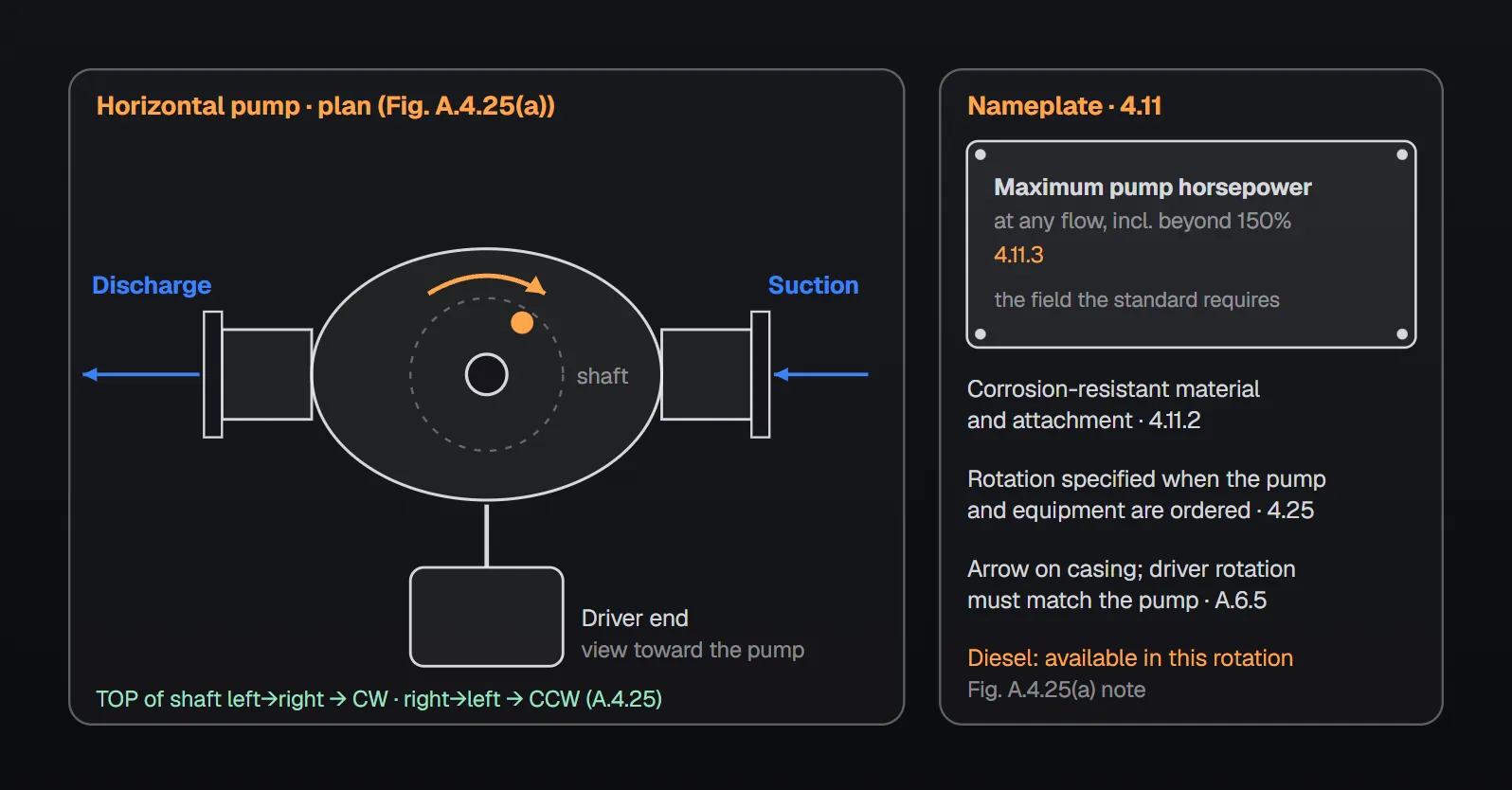
Nameplate (4.11)
- Pumps are provided with a nameplate (4.11.1).
- The nameplate is made of and attached using corrosion-resistant material (4.11.2).
- The nameplate indicates the maximum pump horsepower demand required to power the pump at any flow, including flows beyond 150 percent of rated capacity (4.11.3).
NFPA 20 Handbook (2022) commentary: the nameplate provides the pump’s specific performance data, which must be maintained for the life of the system; without it, the pump’s performance characteristics can be difficult to determine. Nameplates not securely attached or not made of corrosion-resistant material can become lost or illegible over time; the Handbook shows a photo of a partly illegible plate. Its typical nameplate photo shows fields such as rated flow and head, speed, impeller diameter, number of stages, maximum net pressure developed, net pressure at 150 percent capacity, maximum brake horsepower and maximum positive suction pressure; of these the standard explicitly requires only the maximum pump horsepower (4.11.3).
The horsepower value in 4.11.3 feeds other rules. On a self-regulating variable speed unit, the VFD output current marked on the controller nameplate is not exceeded at that horsepower (4.8.7); see self-regulating variable speed pump. The driver is selected to provide the power needed at rated speed and maximum pump load under any flow condition (4.7.6); see pump, driver and controller compatibility.
Shaft rotation (4.25)
The rule is one sentence: pump shaft rotation is determined and correctly specified when fire pumps and equipment involving that rotation are ordered (4.25). Annex A.4.25 explains how to determine it:
- Pumps are designated as right-hand or clockwise (CW), or left-hand or counterclockwise (CCW). Diesel engines are commonly stocked and supplied with clockwise rotation.
- Horizontal pump: stand at the driver end facing the pump. If the top of the shaft revolves from left to right the rotation is clockwise (CW); from right to left, counterclockwise (CCW) [Figure A.4.25(a)].
- Vertical pump: look down at the top of the pump. If the point of the shaft directly opposite revolves from left to right the rotation is clockwise (CW); from right to left, counterclockwise (CCW) [Figure A.4.25(b)].
Figure A.4.25(a) shows two horizontal pumps in plan. Viewed from the driver end, the counterclockwise pump has its suction flange on the left and discharge on the right; the clockwise pump has suction on the right and discharge on the left. The figure notes say diesel engines are available in clockwise rotation and some diesels are available in the other rotation at no extra cost. Figure A.4.25(b) shows a vertical pump from the top, rotating clockwise with suction on the left and discharge on the right.
Why it matters
According to the Handbook (2022) commentary, the rotation of a fire pump dictates the entire layout of piping and equipment in the pump room. The correct rotation must be determined before piping layout and design start and should be specified on the purchase order. Not all manufacturers view rotation from the same perspective, so the manufacturer’s catalog should be consulted for the procedure. Some diesel engine drives are only available in a single rotation. The Handbook also shows a pump with the rotation direction marked on the casing.
Checking rotation on site
Annex A.6.5 (installation and alignment) asks for the driver rotation to be checked against the pump’s; the pump’s rotation is shown by an arrow on the casing. Annex B.1.29 covers wrong rotation: an impeller turning backward is rare but clearly recognizable by an extreme deficiency of pump delivery, and is found by comparing the direction the flexible coupling turns with the arrow on the casing. With a polyphase electric motor two wires are reversed; with a dc driver the armature connections are reversed with respect to the field connections. Where two sources of electrical current are available, the rotation produced by each is checked.
At acceptance, a test for electric motors confirms there is no phase reversal condition on the normal supply or on the alternate supply where provided (14.2.6.12); Annex A.14.2.6.12 accepts a simulated test of the phase reversal device.
Other signals (4.26)
Where required by other sections of the standard, signals call attention to improper conditions in the fire pump equipment (4.26). Annex A.4.26 lists conditions for which signals might be recommended, depending on local conditions, in addition to those required for controllers and engines:
- Low pump room temperature
- Relief valve discharge
- Flowmeter left on, bypassing the pump
- Water level in suction supply below normal
- Water level in suction supply near depletion
- Steam pressure below normal
These additional signals can be incorporated into the trouble signals already provided on the controller, or they can be independent (A.4.26). The source leaves the choice to local conditions. Related: pump room heat, ventilation and drainage, main relief valve, test header and flowmeter.
Common mistakes (from the sources)
- Loose or non-corrosion-resistant nameplate: the Handbook notes it can become lost or illegible (4.11.2).
- Fixing rotation after the piping design: the Handbook wants rotation decided before piping layout and written on the order (4.25).
- Ignoring different manufacturer conventions: the Handbook advises checking the procedure in the manufacturer’s catalog.
- A driver turning the wrong way: Annex B.1.29 describes an extreme deficiency of delivery; compare coupling rotation with the casing arrow.
Checklist
- Nameplate present; material and attachment corrosion resistant (4.11.1, 4.11.2).
- Maximum pump horsepower, including beyond 150%, on the plate (4.11.3).
- Rotation specified on the pump and driver order (4.25).
- Available diesel rotation matches the pump (A.4.25, Handbook).
- Coupling rotation matches the casing arrow (A.6.5, B.1.29).
- Phase reversal test done on normal and alternate supply for electric motors (14.2.6.12).
- Need for additional signals assessed against local conditions (4.26, A.4.26).
Frequently Asked Questions
What must a fire pump nameplate show?
The standard explicitly requires the maximum pump horsepower demand needed to power the pump at any flow, including flows beyond 150 percent of rated capacity (NFPA 20-2025 4.11.3). The plate is made of and attached using corrosion-resistant material (4.11.2).
How is pump shaft rotation determined?
For a horizontal pump, stand at the driver end facing the pump; if the top of the shaft revolves left to right the rotation is clockwise (CW), right to left counterclockwise (CCW). For a vertical pump, look down from the top and follow the point of the shaft directly opposite (A.4.25).
Why is rotation specified on the order?
The rule requires it (4.25). The Handbook (2022) commentary explains that rotation dictates the entire piping and equipment layout of the pump room; some diesel drives come in one rotation only, and diesel engines are commonly stocked clockwise (A.4.25).
What happens if the pump turns the wrong way?
Annex B.1.29 says an impeller turning backward is rare but clearly recognizable by an extreme deficiency of pump delivery. Compare coupling rotation with the casing arrow; on a polyphase motor two wires are reversed.
Which additional signals does 4.26 suggest?
Annex A.4.26 lists low pump room temperature, relief valve discharge, flowmeter left on, low or near-depleted suction supply water level and low steam pressure as conditions for which signals might be recommended, depending on local conditions.

SprinkCalc — Fire Sprinkler Design Across Three Standards
SprinkCalc covers hazard classification, design density and area, K-factor selection, water demand and hydraulic calculations for NFPA 13, FM Global and BS EN 12845 in a single iOS app, and exports a professional PDF report.
Download SprinkCalc on the App Store
MEP Calc — 110+ Engineering Calculators
MEP Calc bundles 110+ engineering modules in one iOS app: 21 fire calculations plus heating, cooling, HVAC, plumbing, steam and natural gas.
Download MEP Calc on the App StoreNFPA 20-2025, Standard for the Installation of Stationary Pumps for Fire Protection: 4.11.1–4.11.3; 4.25; 4.26; 4.7.6; 4.8.7; 14.2.6.12; Annex A.4.25, Figures A.4.25(a), A.4.25(b), A.4.26, A.6.5, A.14.2.6.12, Annex B.1.29 (explanatory). NFPA 20 Handbook 2022 commentary: 4.11 and 4.25.