The NFPA 20 Handbook (2022) calls the centrifugal pump the most common of all pumps for fire protection. NFPA 20-2025 Chapter 6 splits these pumps into two designs: overhung impeller and impeller between bearings. The chapter also states where a centrifugal pump cannot be used, the sealing type, and the fittings that come with or are needed for the pump.
In short: Chapter 6 applies to overhung-impeller and impeller-between-bearings centrifugal pumps (6.1.1.1). Overhung-impeller pumps are close coupled or separately coupled, single- or two-stage end-suction or in-line pumps (6.1.1.2); impeller-between-bearings pumps are separately coupled, single-stage or multistage, axial (horizontal) or radial (vertical) split case (6.1.1.3). They are not used where a static suction lift is required (6.1.1.4), and the sealing type is packing (6.1.1.5). Automatically controlled pumps get a listed float-operated air release valve of at least nominal 0.50 in. (12.7 mm), with an exception (6.3.3.1, 6.3.3.2).
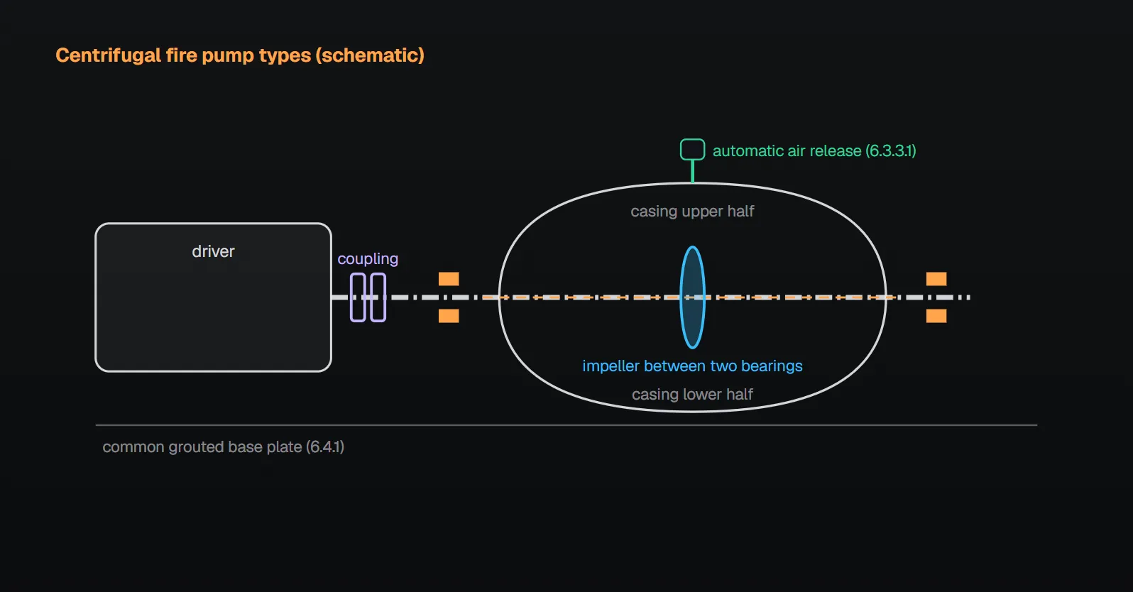
Two designs, seven figures (6.1.1)
Per the NFPA 20 Handbook (2022) commentary, in an overhung impeller design the impeller is at the end of the shaft and the shaft is supported on only one side of the impeller; in an impeller-between-bearings design the shaft extends through the impeller with bearings on both sides to carry the impeller and shaft loads. On a close coupled pump the driver is attached to the pump housing and the impeller is assembled onto the driver shaft; on a separately coupled pump the pump and driver have separate shafts that must be connected.
| Design | Type | Annex figure | Section |
|---|---|---|---|
| Overhung impeller | Close coupled, single stage, end suction | A.6.1.1(a) | 6.1.1.2 |
| Overhung impeller | Separately coupled, single stage, end suction (frame mounted) | A.6.1.1(b) | 6.1.1.2 |
| Overhung impeller | Close coupled, single stage, in-line | A.6.1.1(c) | 6.1.1.2 |
| Overhung impeller | Separately coupled, single stage, in-line: rigid or flexible coupling | A.6.1.1(d), (e) | 6.1.1.2 |
| Impeller between bearings | Separately coupled, single stage, axial (horizontal) split case | A.6.1.1(f) | 6.1.1.3 |
| Impeller between bearings | Separately coupled, single stage, radial (vertical) split case | A.6.1.1(g) | 6.1.1.3 |
Per the Handbook, in an end suction pump water enters at the end of the pump perpendicular to the plane of the impeller; in an in-line pump the drive unit is supported by the pump with suction and discharge flanges on approximately the same centerline; in an axial (horizontal) split-case pump the shaft is in a horizontal plane and the impeller rotates in a vertical plane; in a multistage pump pressure rises as water passes from one impeller to the next. Figure A.6.1.1(h) classifies stationary pumps by mechanical configuration; vertical turbine pumps are in Chapter 7. Multistage multiport pumps: multistage multiport fire pump.
Application limit and sealing (6.1.1.4, 6.1.1.5)
Centrifugal pumps addressed in the chapter are not used where a static suction lift is required (6.1.1.4). Per A.6.1.1.4, the centrifugal pump is particularly suited to boost the pressure from a public or private supply or to pump from a storage tank with a positive static head. The Handbook (2022) gives the reason: a centrifugal pump is not self-priming and will not pump unless water covers the impeller; earlier editions allowed suction lift with a priming water tank, but leaky foot valves losing the priming water made this unreliable, and it was removed beginning with the 1974 edition. Suction pressure limits: fire pump minimum suction pressure.
Per the Handbook, unlike a positive displacement pump, a centrifugal pump reaches a maximum pressure and can run against a closed system indefinitely, provided enough water is discharged to cool it, since the energy imparted is converted to heat (see circulation relief valve).
The sealing type for centrifugal pumps is packing (6.1.1.5); the standard gives no reason. Separate water supply conditions for pumps with mechanical seals are in 4.6.2.1.1 (see water supply adequacy). Performance limits (6.2) are covered separately: pump curve, churn and 150 percent.
Fittings (6.3)
| Fitting | Provided by | Section | Details |
|---|---|---|---|
| Automatic air release valve | Where necessary, pump manufacturer or authorized representative | 6.3.1(1) | 6.3.3 |
| Circulation relief valve | Where necessary, pump manufacturer or authorized representative | 6.3.1(2) | circulation relief |
| Pressure gauges | Where necessary, pump manufacturer or authorized representative | 6.3.1(3) | pressure gauges |
| Eccentric tapered reducer at suction inlet | Where necessary | 6.3.2(1) | suction pipe |
| Hose valve manifold with hose valves | Where necessary | 6.3.2(2) | test header |
| Flow measuring device | Where necessary | 6.3.2(3) | flowmeter |
| Relief valve and discharge cone | Where necessary | 6.3.2(4) | main relief valve |
| Pipeline strainer | Where necessary | 6.3.2(5) | — |
Annex A.6.3.1 points to two figures: Figure A.6.3.1(a) shows a horizontal split-case pump installation with the water supply under a positive head (suction tank, entrance elbow with vortex plate, OS&Y gate valve, eccentric reducer, suction and discharge gauges, automatic air release, discharge check valve, relief valve if required, hose valve manifold); Figure A.6.3.1(b) shows a backflow preventer installation. Per the Handbook, the suction-side gauge should be a compound gauge that reads negative pressure whenever the supply is a ground-level storage tank or has a low residual pressure.
Automatic air release (6.3.3)
Automatically controlled pumps get a listed float-operated air release valve with a nominal 0.50 in. (12.7 mm) minimum diameter, discharged to atmosphere (6.3.3.1). This does not apply to overhung impeller–type pumps with top centerline discharge or that are vertically mounted to naturally vent the air (6.3.3.2). The Handbook (2022) reason: air in the impeller can cause cavitation, damage the impeller and hurt pump performance.
Common field mistakes
- Centrifugal pump lifting from a source below the pump: prohibited by 6.1.1.4; the Handbook explains the old priming-tank arrangement was removed as unreliable.
- No air release valve on a between-bearings pump: contrary to 6.3.3.1 for automatically controlled pumps.
- Air release valve under 0.50 in. (12.7 mm) or not listed: contrary to 6.3.3.1.
- Plain pressure gauge on the suction: the Handbook recommends a compound gauge for ground-level tanks or low residual pressure.
Checklist
- Is the pump one of the types in 6.1.1.2 or 6.1.1.3?
- Does the supply give a positive head with no static suction lift (6.1.1.4, A.6.1.1.4)?
- Is the sealing type packing (6.1.1.5)?
- Are the necessary fittings provided (6.3.1, 6.3.2)?
- Automatically controlled pump: listed float-operated air release valve of at least 0.50 in. (12.7 mm) discharging to atmosphere, or does the 6.3.3.2 exception apply?
Frequently Asked Questions
Which centrifugal pump types does NFPA 20 accept?
Overhung impeller (close coupled or separately coupled, single- or two-stage, end suction or in-line) and impeller between bearings (separately coupled, single-stage or multistage, axial or radial split case) pumps (6.1.1.1–6.1.1.3, Figures A.6.1.1(a)–(g)).
Can a centrifugal fire pump work with suction lift?
No. It is not used where a static suction lift is required (6.1.1.4). Handbook (2022): the pump is not self-priming; the old priming-tank arrangement proved unreliable due to leaky foot valves and was removed beginning with the 1974 edition.
When is an automatic air release valve required?
On automatically controlled pumps: listed, float-operated, nominal 0.50 in. (12.7 mm) minimum diameter, discharged to atmosphere (6.3.3.1). Not required on overhung impeller pumps with top centerline discharge or vertically mounted to naturally vent the air (6.3.3.2).
Which fittings come with the pump?
Where necessary, the automatic air release valve, circulation relief valve and pressure gauges are provided by the pump manufacturer or an authorized representative (6.3.1); the eccentric reducer, hose valve manifold, flow measuring device, relief valve and discharge cone, and pipeline strainer are provided where necessary (6.3.2).
What sealing type is required?
Per NFPA 20-2025 the sealing type for centrifugal pumps is packing (6.1.1.5). Water supply conditions for pumps with mechanical seals are given separately in 4.6.2.1.1.

SprinkCalc — Fire Sprinkler Design Across Three Standards
SprinkCalc covers hazard classification, design density and area, K-factor selection, water demand and hydraulic calculations for NFPA 13, FM Global and BS EN 12845 in a single iOS app, and exports a professional PDF report.
Download SprinkCalc on the App Store
MEP Calc — 110+ Engineering Calculators
MEP Calc bundles 110+ engineering modules in one iOS app: 21 fire calculations plus heating, cooling, HVAC, plumbing, steam and natural gas.
Download MEP Calc on the App StoreNFPA 20-2025, Standard for the Installation of Stationary Pumps for Fire Protection: 4.6.2.1.1; 6.1.1.1–6.1.1.5; 6.3.1–6.3.3.2; Annex A.6.1.1, Figures A.6.1.1(a)–(h), A.6.1.1.4, A.6.3.1, Figures A.6.3.1(a) and (b) (explanatory). NFPA 20 Handbook 2022 commentary: Chapter 6 introduction, 6.1.1.2, 6.1.1.3, 6.1.1.4, 6.3.1, 6.3.3.