An electric fire pump is only as reliable as the power reaching its motor. NFPA 20-2025 Chapter 9 covers the transmission of power from the source to the motor; Section 9.1 gives general rules for all power supplies and Section 9.2 sets out how the normal source of power is connected. The controller, transfer switch and accessories belong to Chapter 10 (9.1.2).
In short: all power supplies are protected against fire, can run the pump continuously and meet the voltage drop limits of 9.4 (9.1.4–9.1.6). No phase converters, no arc fault interruption, and no ground-fault interruption that opens the motor below the current needed to protect the conductors (9.1.7, 9.1.8). The normal power is a continually available source arranged in one of five ways (9.2.1, 9.2.2). In four of them a single disconnecting means with its overcurrent protection is permitted ahead of the controller; it is suitable as service equipment, lockable in both positions, remote, marked in letters at least 1 in. (25 mm) high and supervised closed, and the protection carries the largest motor’s locked rotor current indefinitely (9.2.3–9.2.3.4).
What does Chapter 9 cover?
Chapter 9 covers the sources and transmission of electrical power to motors driving fire pumps and all intermediate equipment between the source and the pump, including the motor, but not the electric fire pump controller, transfer switch and accessories (9.1.1, 9.1.2). All electrical equipment and installation methods comply with Article 695 and other applicable articles of NFPA 70 (9.1.3). Per the NFPA 20 Handbook (2022) commentary, this intermediate equipment includes motors, generators, junction boxes, and fuses, circuit breakers and switches other than those within the controller.
General rules for all power supplies (9.1)
| Rule | Clause | Reasoning (Annex A / Handbook 2022) |
|---|---|---|
| Power supplies are located and arranged to protect against damage by fire from within the premises and exposing hazards | 9.1.4 | Where the supply involves an on-site power production facility, the facility itself is protected in addition to the wiring and equipment (A.9.1.4). Fire damage to conductors or equipment could render the pump inoperable; this includes protecting overhead lines, if used (Handbook). |
| All power supplies can run the pump on a continuous basis | 9.1.5 | A pump can run over a holiday weekend, for many hours in a high-rise fire, or for days to prevent rekindling; no reliable sizing method exists other than continuous duty (Handbook). |
| All power supplies meet the voltage drop rules of Section 9.4 | 9.1.6 | Supply capacity sometimes has to be increased to meet them (Handbook). |
| No phase converters to supply a fire pump | 9.1.7 | Voltage imbalance between phases when there is no load (A.9.1.7). The converter would have to run continuously for the controller to stay in standby; without three-phase power a single-phase controller and motor are used (Handbook). |
| No ground-fault interruption means that opens the motor at current levels less than those required to protect the conductors (see 10.4.5.8) | 9.1.8.1 | Ground fault alarm provisions are not prohibited (A.9.1.8). An alarm reports the fault but pump power is not interrupted; the cause is investigated at once (Handbook). |
| No arc fault interruption means in any fire pump control or power circuit | 9.1.8.2 | Arc-fault devices may alarm but must not interrupt pump power (Handbook). |
Phase converters installed by the power utility in its own transmission lines are outside the scope of the standard; the authority having jurisdiction evaluates the reliability of the supply (A.9.1.7).
Normal power: five permitted arrangements (9.2)
An electric motor-driven fire pump has a normal source of power as a continually available source (9.2.1). The source and its routing follow one of these arrangements (9.2.2):
| Arrangement | Clause | Handbook (2022) commentary |
|---|---|---|
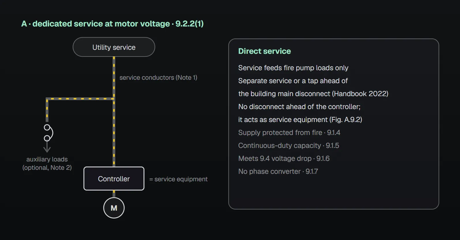
| Service connection dedicated to the fire pump installation | 9.2.2(1) | The service supplies no loads other than the fire pump’s; it is a separate service or a tap ahead of the building main service disconnect. Fire departments frequently shut down building power during a fire; pump power must remain. |
| On-site power production facility connection dedicated to the fire pump installation | 9.2.2(2) | An on-site standby or emergency generator does not qualify: a production facility is constantly producing power, a standby generator is not (3.3.48.2, 3.3.48.3). |
| Dedicated feeder derived directly from the dedicated service to the fire pump installation | 9.2.2(3) | Supplies no loads other than the fire pump’s; those loads are tapped ahead of the controller, not from within it. |
| Feeder connection where all are met: (a) multibuilding campus-style arrangement, (b) backup source independent of the normal source, (c) arrangements (1)–(3) impractical, (d) acceptable to the AHJ, (e) overcurrent protection in each disconnecting means selectively coordinated with the supply side devices | 9.2.2(4) | This feeder may supply other loads; with the required backup source and selective coordination it is not considered less reliable. Selective coordination keeps an overcurrent in the pump branch from interrupting loads served by upstream devices. |
| Dedicated transformer connection directly from the service, meeting Article 695 of NFPA 70 | 9.2.2(5) | The transformer is dedicated to the fire pump and serves no unrelated loads. |
Annex A.9.2 shows typical routings in Figure A.9.2: A, service at motor utilization voltage straight to the controller; B, service at another voltage through service equipment and a transformer; C, service at motor utilization voltage through service entrance equipment (the 9.2.3 disconnect) and a dedicated feeder (9.2.2(3)). In each, fire pump auxiliary loads may optionally be tapped ahead of the controller through their own overcurrent protection. Per the Handbook (2022), in A the controller acts as service equipment; in B the transformer steps the service voltage down to motor voltage; in C the disconnect is normally remote from the pump room.
Single disconnect and overcurrent protection (9.2.3)
With arrangement 9.2.2(1), (2), (3) or (5), a single disconnecting means and associated overcurrent protection device is permitted in the supply to the controller (9.2.3). Per the Handbook (2022), this disconnect is for activities such as maintenance, not for operation under fire; more disconnects reduce reliability, may be remote and hard to find, and are hard to supervise during a fire. Where installed, the disconnect:
- Is identified as suitable for use as service equipment (9.2.3.1(1)).
- Is lockable in both the closed and the open position (9.2.3.1(2)). Handbook: most disconnects lock only in the open position; a field-installed locking accessory may be needed.
- Is remote from other building disconnects and from other fire pump source disconnects (9.2.3.1(3), (4)), so that inadvertent simultaneous operation is not likely (A.9.2.3.1(3), (4)). The Handbook treats “remote” as not within sight of the others, for example a different room or separation by construction.
- Is marked “Fire Pump Disconnecting Means” in letters at least 1 in. (25 mm) high, visible without opening doors or covers (9.2.3.1(5)).
- Has a placard next to the controller stating its location and the location of any key (9.2.3.2).
- Is supervised closed by one of: central station, proprietary or remote station signal; local signaling at a constantly attended location; locking closed; or, within fenced enclosures or owner-controlled buildings, sealing plus approved weekly recorded inspections (9.2.3.3).
Sizing the overcurrent protection
The device carries indefinitely the sum of the locked rotor current of the largest pump motor and the full-load current of all other pump motors and accessory equipment (9.2.3.4). Alternatively, an assembly listed for fire pump service meets all of the following (9.2.3.4.1):
| Condition (9.2.3.4.1) | Value |
|---|---|
| (1) Must not open at 600 percent full-load current | within 2 minutes |
| (2) Restart transient | does not open at 24 times full-load current |
| (3) Must not open at 300 percent full-load current | within 10 minutes |
| (4) Circuit breaker trip point | not field adjustable |
| (5) Identification | “Suitable for Use as Service Equipment” |
| (6) Disconnect marking where used as service equipment | “Service Disconnect” |
An instantaneous trip circuit breaker may be part of this assembly (9.2.3.4.1.1). Arc-resistant rated equipment is provided for the protective device of 9.2.3.4 or 9.2.3.4.1 (9.2.3.4.2). Handbook (2022) reasoning: on overload, the circuit breaker in the controller should be the only device to disconnect the motor; an overload may be temporary and that breaker can be reset, whereas an upstream device that opens could not be reset or replaced in time to fight the fire. Locked rotor current is typically 600 percent or more of full-load current.
Common field mistakes
- Feeding the pump from the building main service: the Handbook (2022) does not accept it; the pump needs a dedicated connection, or it may be shut down during fire fighting (9.2.2(1)).
- Counting a standby generator as normal power: a generator that is not constantly producing is not a 9.2.2(2) facility (3.3.48.3).
- Phase converters: prohibited by 9.1.7.
- Pump disconnect beside the building disconnects, or lockable only open: contrary to 9.2.3.1(2)–(4).
- Sizing the upstream protection on full-load current: 9.2.3.4 requires carrying locked rotor current indefinitely.
Checklist
- Which arrangement of 9.2.2(1)–(5); if (4), are all five conditions documented?
- Supply and wiring protected from fire, capacity for continuous running (9.1.4, 9.1.5).
- No phase converter, no arc fault interruption, no ground-fault device opening the motor (9.1.7, 9.1.8).
- At most one disconnect ahead of the controller: service rated, lockable both ways, remote, marked, placarded, supervised (9.2.3–9.2.3.3).
- Upstream protection carries locked rotor current indefinitely or is a listed assembly per 9.2.3.4.1; arc-resistant (9.2.3.4–9.2.3.4.2).
- Voltage drop checked per 9.4 (9.1.6).
Frequently Asked Questions
Can a fire pump be fed from the building main switchboard?
NFPA 20-2025 9.2.2 lists five arrangements: dedicated service, dedicated on-site power production facility, dedicated feeder from the dedicated service, a conditional campus feeder and a dedicated transformer. The NFPA 20 Handbook (2022) does not accept the building main service; the pump could lose power when the building is shut down during fire fighting.
Can a standby generator be the normal source?
No. 9.2.2(2) requires an on-site power production facility that constantly produces power (3.3.48.2); an on-site standby generator does not (3.3.48.3). A generator is used as an alternate source (9.3.3(1), Section 9.6).
How many disconnects may be ahead of the controller?
With arrangement 9.2.2(1), (2), (3) or (5), a single disconnecting means and its overcurrent protection is permitted (9.2.3). It is service rated, lockable in both positions, remote, marked in letters at least 1 in. (25 mm) high, placarded and supervised closed (9.2.3.1–9.2.3.3).
How is the upstream fuse or breaker sized?
To carry indefinitely the locked rotor current of the largest pump motor plus the full-load current of the other motors and accessory equipment (9.2.3.4), or as a listed assembly that does not open within 2 minutes at 600 percent, within 10 minutes at 300 percent, or on a restart transient of 24 times full-load current (9.2.3.4.1).
Is ground-fault protection allowed in a fire pump circuit?
A ground-fault interruption means that opens the motor at current levels below those needed to protect the conductors is not permitted (9.1.8.1), and no arc fault interruption means is installed (9.1.8.2). Ground fault alarms are not prohibited (A.9.1.8).

SprinkCalc — Fire Sprinkler Design Across Three Standards
SprinkCalc covers hazard classification, design density and area, K-factor selection, water demand and hydraulic calculations for NFPA 13, FM Global and BS EN 12845 in a single iOS app, and exports a professional PDF report.
Download SprinkCalc on the App Store
MEP Calc — 110+ Engineering Calculators
MEP Calc bundles 110+ engineering modules in one iOS app: 21 fire calculations plus heating, cooling, HVAC, plumbing, steam and natural gas.
Download MEP Calc on the App StoreNFPA 20-2025, Standard for the Installation of Stationary Pumps for Fire Protection: 3.3.48.2, 3.3.48.3; 9.1.1–9.1.8.2; 9.2.1–9.2.3.4.2; Annex A.9.1.4, A.9.1.7, A.9.1.8, A.9.2 and Figure A.9.2, A.9.2.3.1(3), A.9.2.3.1(4) (explanatory). NFPA 20 Handbook 2022 commentary: Sections 9.1 and 9.2.