The pump will not deliver, it overheats, vibrates or draws too much power: where to start? NFPA 20-2025 Annex B gives a troubleshooting chart for this: 10 troubles, 32 possible causes and a suggested remedy for each cause. The annex is informational and not part of the requirements.
In short: Figure B.1 maps each trouble to its possible causes, grouped as suction (1–4), pump (5–20), driver and/or pump (21–25) and driver (26–32). The causes are in addition to mechanical breakage that would be obvious on visual inspection, and troubles that are easy to check should be corrected or eliminated first (B.1). Annex B.3 explains how to return an electric fire pump controller to service after a fault.
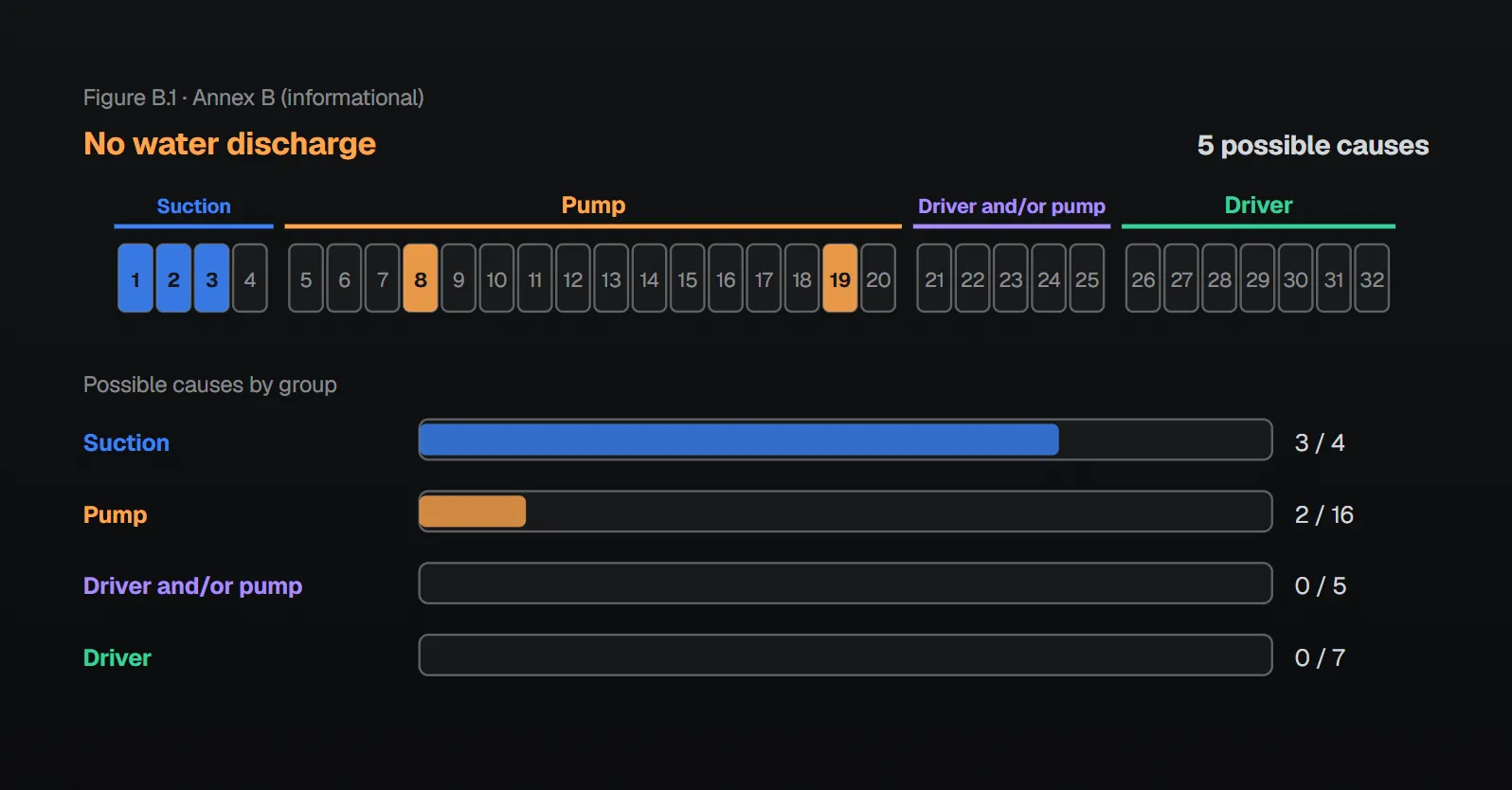
Troubles and possible causes
| Trouble | Suction (1–4) | Pump (5–20) | Driver and/or pump (21–25) | Driver (26–32) |
|---|---|---|---|---|
| Excessive leakage at stuffing box | — | 5, 18 | 23 | — |
| Pump or driver overheats | 4 | 5, 6, 8, 11, 15, 18, 19, 20 | 21, 22, 23, 24, 25 | 27, 29, 30, 31 |
| Pump unit will not start | 4 | 5, 15, 16, 17 | 21 | 26, 27, 32 |
| No water discharge | 1, 2, 3 | 8, 19 | — | — |
| Pump is noisy or vibrates | 4 | 5, 8, 10, 18 | 21, 22, 23, 24 | 27 |
| Too much power required | 4 | 5, 8, 9, 11, 13, 15, 18 | 21, 22, 23, 24 | 27, 29, 30, 31 |
| Discharge pressure not constant for same gpm | 1 | 5, 6, 7 | — | — |
| Pump loses suction after starting | 1, 2, 3 | 6, 7, 20 | — | — |
| Insufficient water discharge | 1, 2, 3 | 6, 7, 8, 9, 10, 11, 12, 13, 15 | — | 28, 29, 31 |
| Discharge pressure too low for gpm discharge | 1, 2, 3 | 5, 6, 7, 8, 9, 10, 11, 12, 13, 14 | — | 28, 29, 31 |
Annex B.1 calls the chart a partial guide and the remedies a partial list. The NFPA 20 Handbook (2022) notes that Annex B may be useful in identifying and correcting problems discovered during acceptance tests.
Causes and suggested remedies
| No | Possible cause | Annex B remedy (summary) |
|---|---|---|
| Suction | ||
| 1 | Air drawn into suction connection through leak(s) | Uncover suction pipe, locate and repair leak |
| 2 | Suction connection obstructed | Examine intake, screen and pipe; remove obstruction (see 4.16.8) |
| 3 | Air pocket in suction pipe | Uncover and rearrange suction pipe (see 4.16.6) |
| 4 | Well collapsed or serious misalignment | Consult a well driller and the pump manufacturer |
| Pump | ||
| 5 | Stuffing box too tight or packing improper, worn, defective or wrong type | Remove gland halves, replace packing |
| 6 | Water seal or pipe to seal obstructed | Remove seal ring and packing, clean water passage |
| 7 | Air leak into pump through stuffing boxes | Same as B.1.6 |
| 8 | Impeller obstructed | Open pump, clear impeller; screen the intake |
| 9 | Wearing rings worn | Check ring clearance with a feeler gauge |
| 10 | Impeller damaged | Minor repair or replacement from manufacturer |
| 11 | Wrong diameter impeller | Replace with impeller of proper diameter |
| 12 | Actual net head lower than rated | Check impeller diameter, number and model for correct curve |
| 13 | Casing gasket defective, internal leakage (single- and multistage) | Replace gasket; check drawing whether required |
| 14 | Pressure gauge on top of pump casing | Place gauges correctly [see Figure A.6.3.1(a)] |
| 15 | Incorrect impeller adjustment (vertical turbine only) | Adjust impellers per manufacturer |
| 16 | Impellers locked | Turbine: raise/lower by top nut; split case: remove obstruction |
| 17 | Pump is frozen | Heat the pump room; disassemble, remove ice, inspect |
| 18 | Shaft or shaft sleeve scored, bent or worn | Replace shaft or sleeve |
| 19 | Pump not primed | Shut down; on a turbine check submergence |
| 20 | Seal ring improperly located in stuffing box | Reinstall seal ring in proper location |
| Driver and/or pump | ||
| 21 | Excess bearing friction (lubrication, wear, dirt, rust, failure, installation) | Remove bearings; clean, lubricate or replace |
| 22 | Rotating element binds against stationary element | Check clearances and lubrication; repair part |
| 23 | Pump and driver misaligned | Align per manufacturer, replace bearings (see Section 6.5) |
| 24 | Foundation not rigid | Tighten bolts or replace foundation (see Section 6.4) |
| 25 | Engine-cooling system obstructed | Check regulator valve, strainer and cooling circuit |
| Driver | ||
| 26 | Faulty driver | Check driver per manufacturer's instructions |
| 27 | Lack of lubrication | Replace seized parts, lubricate |
| 28 | Speed too low | Check speed, voltage, frequency and starting equipment |
| 29 | Wrong direction of rotation | Compare coupling rotation with casing arrow |
| 30 | Speed too high | Match rated speeds; set governor |
| 31 | Rated motor voltage different from line voltage | Correct voltage or larger motor (see Section 9.4) |
| 32 | Faulty circuit, obstructed fuel system or steam pipe, dead battery | Check wiring, switch, breaker, battery, fuel line, strainers |
Numerical and diagnostic hints in Annex B
- Wearing rings (B.1.9): clearance when new is 0.0075 in. (0.19 mm); more than 0.015 in. (0.38 mm) is excessive.
- Obstructed impeller (B.1.8): does not show on any one instrument, but pressures fall off rapidly when a large flow is drawn.
- Pump not primed (B.1.19): run without water in its casing, the wearing rings are likely to seize; the first warning is a change in pitch of the driver’s sound.
- Cooling (B.1.25): if overheating persists at loads up to 150 percent of rated capacity, contact the pump or engine manufacturer.
- Reverse rotation (B.1.29): rare but clearly recognizable by an extreme deficiency of delivery; compare the flexible coupling’s rotation with the arrow on the pump casing. With a polyphase motor two wires are reversed; where two power sources exist, check the rotation produced by each.
- Voltage mismatch (B.1.31): the example given is a 220 V or 440 V motor on a 208 V or 416 V line.
- Speed too low (B.1.28): low frequency and low voltage in the power supply keep a motor from reaching rated speed; on an internal combustion engine drive check the governor setting and that the hand throttle is wide open.
In a note based on NFPA 25, the Handbook (2022) lists a plugged impeller, worn wear rings and obstructed suction among the most common causes of reduced capacity; the suction gauge reading can show whether the trouble is in the water supply or suction pipe, while the difference between suction and discharge gauge readings can point to a plugged impeller or overly worn wear rings.
Controller after a fault (B.2, B.3)
- Chapters 9 and 10 discourage disconnecting means in the power supply to electric motor–driven fire pumps to keep power available; a person servicing equipment on those circuits can therefore have unusual exposure to electrical hazards, and special safe work practices or personal protective clothing may be needed (B.2).
- In a properly installed and coordinated circuit, tripping of the circuit breaker or isolating switch indicates a fault beyond operating overload; qualified personnel inspect and repair the controller (B.3.1).
- All inspections and tests are made with the controller de-energized at the line terminal, disconnected, locked out and tagged (B.3.2).
- Substantial enclosure damage such as deformation, displaced parts or burning means replacing the entire controller (B.3.2.1). If the breaker has opened several short-circuit faults or shows deterioration, replace the components; verify the external handle can open and close the breaker and isolating switch (B.3.2.2).
- Terminals and conductors showing arcing or overheating, and heat-damaged contactor contacts, are replaced (B.3.2.3, B.3.2.4). Before return to service check connection tightness and the absence of short circuits, ground faults and leakage current; close the enclosure before energizing (B.3.2.5).
Checklist
- Find the trouble in Figure B.1; eliminate the easy-to-check causes first (B.1).
- Suction (1–4): leaks, obstruction, air pocket.
- Pump (5–20): packing, impeller, wearing rings, gauge location, priming.
- Driver (21–32): alignment, foundation, cooling, speed, rotation, voltage, battery and fuel.
- If the controller breaker tripped, apply B.3 with the controller de-energized, locked out and tagged.
For gauge location see the pressure gauges article; for the acceptance test see the field acceptance test article.
Frequently Asked Questions
What can cause a fire pump to deliver no water?
Per Figure B.1: air drawn in through suction leaks (1), obstructed suction (2), an air pocket in the suction pipe (3), an obstructed impeller (8) and the pump not primed (19) (NFPA 20-2025 Annex B).
What should be checked when discharge pressure is too low for the flow?
Figure B.1 lists 16 causes: suction (1–3), packing and seal (5–7), impeller and wearing rings (8–11), net head (12), casing gasket (13), gauge on top of the casing (14), low speed (28), wrong rotation (29) and motor voltage mismatch (31).
What wearing ring clearance is acceptable?
Per Annex B.1.9, 0.0075 in. (0.19 mm) when new; more than 0.015 in. (0.38 mm) is excessive.
How is reverse rotation recognized?
Delivery is extremely deficient; compare the flexible coupling’s rotation with the arrow on the pump casing. With a polyphase motor two wires are reversed (B.1.29).
Is Annex B mandatory?
No. Annex B is informational and describes itself as a partial guide (B.1).

SprinkCalc — Fire Sprinkler Design Across Three Standards
SprinkCalc covers hazard classification, design density and area, K-factor selection, water demand and hydraulic calculations for NFPA 13, FM Global and BS EN 12845 in a single iOS app, and exports a professional PDF report.
Download SprinkCalc on the App Store
MEP Calc — 110+ Engineering Calculators
MEP Calc bundles 110+ engineering modules in one iOS app: 21 fire calculations plus heating, cooling, HVAC, plumbing, steam and natural gas.
Download MEP Calc on the App StoreNFPA 20-2025, Standard for the Installation of Stationary Pumps for Fire Protection: Annex B (informational) B.1, B.1.1–B.1.32, Figure B.1, B.2, B.3.1–B.3.2.5. NFPA 20 Handbook 2022 commentary: Chapter 14 introduction; 14.4 Closer Look note; Annex B Figure B.1.