The field acceptance test shows that the installed fire pump works to the standard on site, with its own water supply, driver and controller. NFPA 20-2025 covers it in 14.2. Before the test, the piping has been flushed and hydrostatically tested (see fire pump flushing and hydrostatic test). Per the NFPA 20 Handbook (2022) commentary, the acceptance test forms a baseline, including the water supply characteristics, for later performance testing under NFPA 25.
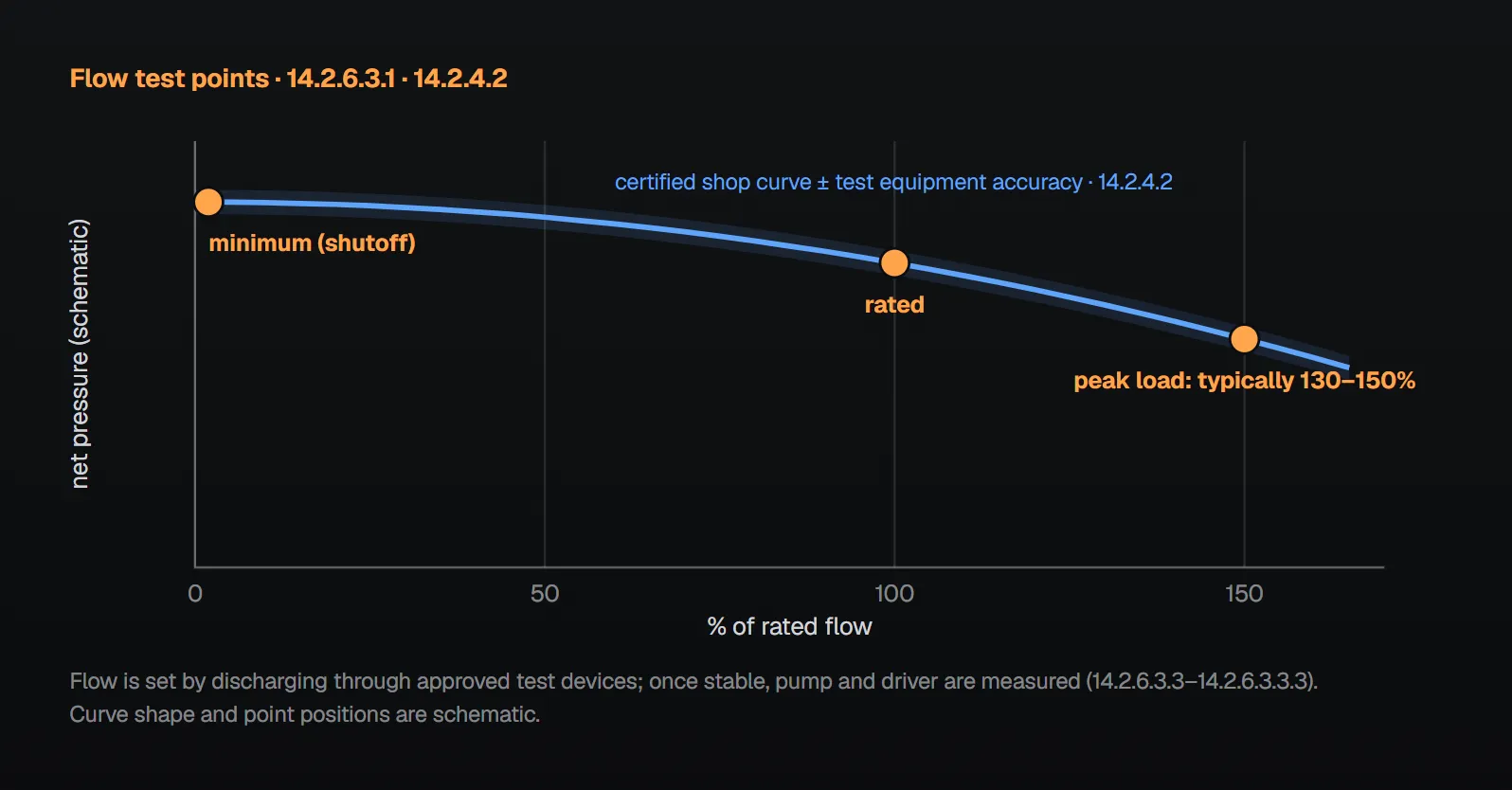
In short: the pump, engine (when supplied), controller and transfer switch (when supplied) manufacturers or their factory-authorized representatives attend (14.2.1). The pump performs at minimum, rated and peak loads without objectionable overheating and equals the certified shop curve at all flows tested (14.2.6.3.1, 14.2.4.2). Calibrated test equipment is used (14.2.6.1.1). The controller gets at least 6 automatic and 6 manual operations, and an electric pump runs at least 5 minutes at full speed each time (14.2.7.2, 14.2.7.3). The pump runs for at least 1 hour in total during all tests (14.2.11).
Who attends and what is ready (14.2.1 through 14.2.5)
- The pump manufacturer, the engine manufacturer (when supplied), the controller manufacturer and the transfer switch manufacturer (when supplied), or their factory-authorized representatives, are present (14.2.1). Per Annex A.14.2.1, representatives of the installing contractor, insurance company and owner should also be present. Handbook (2022): 14.2.1 can be met by a single factory-authorized representative.
- The date, time and location of the test are coordinated with the authority having jurisdiction (14.2.2).
- All electric wiring to the fire pump motors, including control interwiring for multiple pumps, normal and any alternate power supply and the jockey pump, is completed and checked by the electrical contractor before initial startup and acceptance (14.2.3). An arc flash risk assessment per NFPA 70E or an approved local equivalent is performed for all electric controllers, and they are field labeled (14.2.3.1, 14.2.3.2).
- A copy of the manufacturer’s certified pump test curve is available for comparison (14.2.4.1). Details: fire pump unit performance and shop test.
- The actual unadjusted discharge flows and pressures meet or exceed the maximum fire protection demand (14.2.5). Handbook (2022): a pump can perform satisfactorily yet still miss the demand, for example if supply residual pressures have dropped.
Test equipment (14.2.6.1)
| Rule | Clause |
|---|---|
| Calibrated equipment for net pump pressures, flow through the pump, volts and amperes, and speed | 14.2.6.1.1 |
| Gauges, transducers and other devices labeled with the latest calibration date | 14.2.6.1.2 |
| Calibrated annually at minimum; calibration maintained at ±1 percent accuracy | 14.2.6.1.2.1, 14.2.6.1.2.2 |
| Controller voltage and current readings factory calibrated and adjusted to ±2 percent may replace calibrated volt/amp meters | 14.2.6.1.2.3 |
| Fixed outlet flow devices inspected for damage, no calibration required | 14.2.6.1.2.4 |
| Visible orifices are visually inspected and undamaged; discharge orifices are listed or built to a standard with a known coefficient | 14.2.6.1.3, 14.2.6.1.4 |
| NFPA 70E personal protective equipment and procedures near energized electrical or rotating equipment | 14.2.6.1.5 |
Per Annex A.14.2.6.1, most test equipment used for acceptance and annual tests has never been calibrated and can have reading errors of 15 to 30 percent. Any automated inspection and testing devices are themselves tested for accuracy (14.2.6.2): automated testing and monitoring.
Flow test (14.2.6.3)
- The pump performs at minimum, rated and peak loads without objectionable overheating of any component (14.2.6.3.1); vibration is not of a magnitude to damage any component (14.2.6.3.2).
- Minimum, rated and peak loads are set by controlling the water discharged through approved test devices (14.2.6.3.3). The discharge is determined and stabilized, and immediately thereafter the pump and driver operating conditions are measured (14.2.6.3.3.2, 14.2.6.3.3.3).
- Where simultaneous operation of multiple pumps is possible or required, the test includes a flow test of all pumps running together (14.2.6.3.3.1).
- If the supply cannot provide 150 percent of rated flow, the pump runs at the greater of 100 percent of rated flow and the maximum system demand; this reduced test is acceptable if the discharge exceeds the system design flow (14.2.6.3.4, 14.2.6.3.4.1).
- At all flows tested, the installed pump equals the certified shop curve within the accuracy limits of the test equipment (14.2.4.2).
Per the sample procedure in Annex A.14.2.6.3, the important test points are 150 percent, rated and shutoff; readings are corrected to rated speed and plotted. Per the Handbook (2022) commentary, acceptance testing cannot be done with a closed-loop flowmeter: the pump runs at 100 and 150 percent without recirculating water to the suction, which tests both the pump and the water supply. Per Annex A.3.3.47 the maximum power requirement typically occurs between 130 and 150 percent of rated flow. The Handbook adds that peak load is the flow requiring the most horsepower and may occur below 150 percent; if overheating occurs, the test stops and, once fixed, a retest with all flows and a full 1-hour duration is required. Curve criteria: pump curve: churn and 150 percent; test devices: test header and flowmeter.
Special cases have their own clauses: break tank refill rate (14.2.6.3.5), water level detection for vertical turbine pumps in wells (14.2.6.3.6), variable speed pumps (14.2.6.4), multistage multiport pumps (14.2.6.5) and positive displacement pumps (14.2.6.6; see break tank, multistage multiport pump).
Driver checks (14.2.6.7 through 14.2.6.12)
| Driver / test | Rule | Clause |
|---|---|---|
| Electric motor at rated voltage and frequency | Amperes on each phase do not exceed the service factor amperes on the nameplate or manufacturer’s documentation; without them, full-load amperes times the allowable service factor | 14.2.6.7.1, 14.2.6.7.1.1 |
| Electric motor under varying voltage | Actual voltage × current on each phase does not exceed rated voltage × service factor amperes | 14.2.6.7.2, 14.2.6.7.2.1 |
| Voltage at motor contactor output lugs | Within 5 percent below to 10 percent above nameplate voltage during the test | 14.2.6.7.3 |
| Diesel engine | Electrolyte added to dry charge batteries at least 24 hours before starting, with a conditioning charge; no signs of overload or stress; governor set at the test to rated pump speed | 14.2.6.8.1 through 14.2.6.8.3 |
| Steam turbine | Speed within 13.2.2 limits; emergency governor operated | 14.2.6.9, 14.2.9 |
| Right angle gear drive | Operates without excessive objectionable noise, vibration or heating | 14.2.6.10 |
| Loads start test | Unit started and brought to rated speed without interruption with discharge equal to peak load | 14.2.6.11 |
| Phase reversal (electric motor) | No phase reversal on the normal supply or on the alternate supply where provided | 14.2.6.12 |
Per Annex A.14.2.6.12, a simulated test of the phase reversal device is acceptable. For steam turbines see steam turbine-driven fire pumps.
Controller acceptance test (14.2.7, 14.2.8)
- Controllers are tested to the manufacturer’s recommended procedure (14.2.7.1). Per Annex A.14.2.7.1, controller starts required for the tests in 14.2.6 through 14.2.9 count toward this number.
- At least 6 automatic and 6 manual operations are performed (14.2.7.2). An electric pump runs at least 5 minutes at full speed each time (14.2.7.3); a variable speed pump has no minimum run time (14.2.7.3.1).
- An engine need not run 5 minutes at full speed between successive starts until cumulative cranking reaches 45 seconds (14.2.7.4); diesel controller tests are divided between both sets of batteries (14.2.7.7).
- The automatic sequence starts the pump from all provided starting features, including pressure switches or remote starting signals (14.2.7.5, 14.2.7.6).
- Selection, size and setting of all overcurrent protective devices, including the controller circuit breaker, are confirmed (14.2.7.8). The pump is started once from each power service and runs at least 5 minutes; for manual emergency operation the handle is moved to fully latched in one continuous motion (14.2.7.9).
- With an alternate source and automatic transfer switch, loss of normal power is simulated; the standby generator (where provided) starts and power transfers while the pump runs at peak load (14.2.8.1). Transfer and retransfer do not open overcurrent devices, and at least half of the operations are on the alternate source (14.2.8.2, 14.2.8.3). Details: fire pump transfer switch design.
Signals, duration and ECM (14.2.10 through 14.2.12)
Local and remote signals and fire pump alarm conditions are simulated to demonstrate satisfactory operation (14.2.10). The fire pump or foam concentrate pump runs for at least 1 hour in total during all tests (14.2.11); per Annex A.14.2.11, water need not flow for the full hour if all flow tests can be done in less time and the pump is kept from overheating. Engines with electronic fuel management (ECM) get a function test of both primary and alternate ECM (14.2.12).
Common field mistakes
- Testing with gauges that carry no calibration label: 14.2.6.1.2 requires a label with the latest calibration date.
- Accepting a centrifugal pump on a closed-loop flowmeter: per the Handbook (2022), water is not recirculated to the suction during acceptance; 14.2.6.3.3 sets flow by discharging through approved test devices.
- Accepting the controller on fewer than six starts: 14.2.7.2 requires at least 6 automatic and 6 manual.
- Phase reversal test on normal power only: 14.2.6.12 covers the alternate supply too.
- Testing without manufacturer representatives: contrary to 14.2.1.
Checklist
- Manufacturer representatives, AHJ coordination, wiring complete, arc flash label (14.2.1 through 14.2.3.2).
- Certified curve on hand; unadjusted results meet the maximum demand (14.2.4.1, 14.2.5).
- Calibrated, labeled equipment at ±1 percent; orifices inspected (14.2.6.1.1 through 14.2.6.1.4).
- Minimum, rated, peak load; no overheating or damaging vibration; equals the curve (14.2.6.3.1, 14.2.6.3.2, 14.2.4.2).
- Driver checks: amperes, voltage −5/+10 percent, engine, loads start, phase reversal (14.2.6.7 through 14.2.6.12).
- 6 automatic + 6 manual; 5 minutes for electric; diesel battery sets; start from each power service; alternate source (14.2.7.2 through 14.2.8.3).
- Signals simulated; at least 1 hour in total; ECM test (14.2.10 through 14.2.12).
Frequently Asked Questions
Who must attend the fire pump acceptance test?
The pump, engine (when supplied), controller and transfer switch (when supplied) manufacturers or their factory-authorized representatives (14.2.1); per Annex A.14.2.1, also the installing contractor, insurance company and owner. Date, time and location are coordinated with the authority having jurisdiction (14.2.2).
At what flows is the pump run during acceptance?
At minimum, rated and peak loads (14.2.6.3.1), set by discharging through approved test devices (14.2.6.3.3). If the supply cannot give 150 percent, at the greater of 100 percent of rated flow and the maximum system demand (14.2.6.3.4). Annex A.14.2.6.3 names 150 percent, rated and shutoff as the important points.
How many times is the controller operated?
At least 6 automatic and 6 manual operations (14.2.7.2). An electric pump runs at least 5 minutes at full speed each time (14.2.7.3); with an alternate source, at least half of the operations use it (14.2.8.3). Diesel controller tests are divided between both battery sets (14.2.7.7).
How long does the acceptance test last?
The pump runs for at least 1 hour in total during all tests (14.2.11). Per Annex A.14.2.11, water need not flow for the full hour if all flow tests can be done in less time and overheating is prevented.
How accurate must the test equipment be?
Calibrated devices labeled with the latest calibration date, calibrated at least annually and kept at ±1 percent accuracy (14.2.6.1.2 through 14.2.6.1.2.2). Controller voltage and current readings factory calibrated to ±2 percent may replace volt/amp meters (14.2.6.1.2.3).

SprinkCalc — Fire Sprinkler Design Across Three Standards
SprinkCalc covers hazard classification, design density and area, K-factor selection, water demand and hydraulic calculations for NFPA 13, FM Global and BS EN 12845 in a single iOS app, and exports a professional PDF report.
Download SprinkCalc on the App Store
MEP Calc — 110+ Engineering Calculators
MEP Calc bundles 110+ engineering modules in one iOS app: 21 fire calculations plus heating, cooling, HVAC, plumbing, steam and natural gas.
Download MEP Calc on the App StoreNFPA 20-2025, Standard for the Installation of Stationary Pumps for Fire Protection: 14.2.1–14.2.5; 14.2.6.1.1–14.2.6.1.5; 14.2.6.2; 14.2.6.3.1–14.2.6.3.6; 14.2.6.4–14.2.6.6; 14.2.6.7.1–14.2.6.12; 14.2.7.1–14.2.7.9; 14.2.8.1–14.2.8.3; 14.2.9.1, 14.2.9.2; 14.2.10–14.2.12; Annex A.3.3.47, A.14.2.1, A.14.2.6.1, A.14.2.6.3, A.14.2.6.12, A.14.2.7.1, A.14.2.11 (explanatory). NFPA 20 Handbook 2022 commentary: Chapter 14 introduction, 14.2.1, 14.2.5, 14.2.6.3.1, 14.2.6.3.3.