The device that moves an electric fire pump to the alternate source when normal power fails is the power transfer switch. NFPA 20-2025 Section 10.8 sets out the arrangements in which the switch is combined with the controller and the features it must have. When an alternate source is required and on-site generators are covered in separate articles; this one is about the switch only.
In short: the transfer switch is automatic; manual transfer switches are not used (10.8.1.2) and the switch is specifically listed for fire pump service (10.8.3.1). Each fire pump has its own dedicated switch (10.8.2.3). Its ampere rating is at least 115 percent of motor full-load current and it can switch the locked rotor current (10.8.3.4). When the voltage on any phase of the normal source falls below 85 percent of motor-rated voltage, the switch starts the generator (where provided) and initiates transfer (10.8.3.6.2). The switching mechanism has no short-circuit or overcurrent protection (10.8.3.11). An individually listed switch (Arrangement II-A, II-B) is the delayed transition type with a maximum delay of 3 seconds (10.8.2.2(7)).
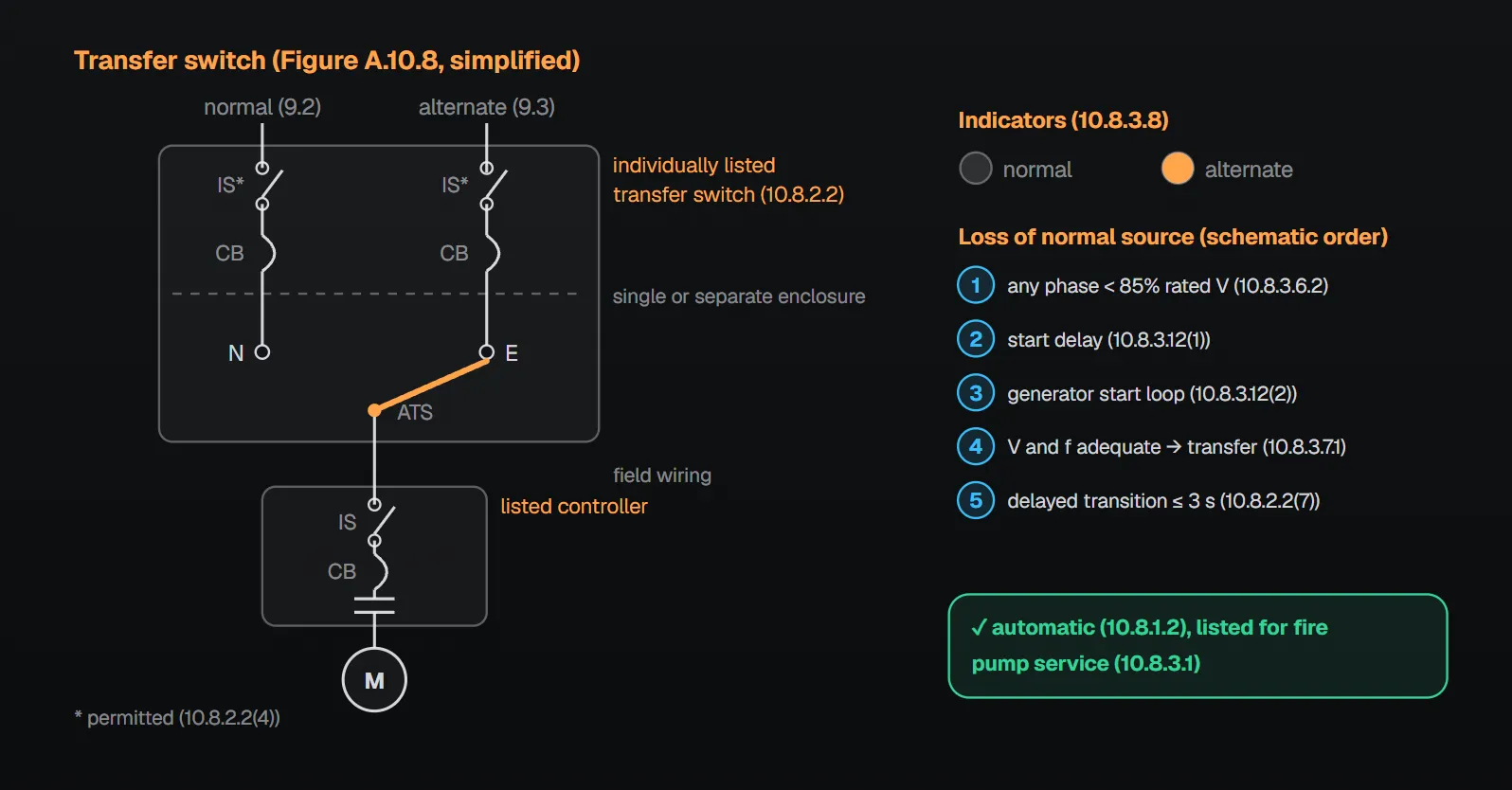
When and where is it used?
- Where required by the authority having jurisdiction, or to meet 9.3.2 where an on-site electrical power transfer device is used for power source selection, the switch complies with Section 10.8 as well as 10.1, 10.2, 10.3 and 10.4.1 (10.8.1.1).
- Manual transfer switches are not used between the normal and alternate supply (10.8.1.2).
- No remote device that would prevent automatic operation of the switch is installed (10.8.1.3).
- Transfer between the normal supply and one alternate supply takes place within the pump room (9.6.4).
- Where a transfer switch is required, each fire pump has its own dedicated switch (10.8.2.3).
Per the NFPA 20 Handbook (2022) commentary, a transfer switch is used when the normal power source is unreliable and moves the motor to an alternate source when normal power is interrupted; all transfer switches in fire pump applications must be automatic. A device such as remote sensing that inhibits operation reduces the reliability of the transfer. On “dedicated”, the Handbook explains that a switch may supply more than one fire pump only through downstream switches; switches upstream of the dedicated switch are outside the scope of NFPA 20.
Three arrangements (Figure A.10.8)
| Arrangement | What | Main clauses |
|---|---|---|
| I | Listed combination fire pump controller and power transfer switch | 10.8.2.1.1–10.8.2.1.5 |
| II-A | Individually listed power transfer switch + fire pump controller | 10.8.2.2(1)–(7) |
| II-B | Individually listed power transfer switch + listed combination controller and transfer switch | 10.8.2.2(1)–(7) |
Per Annex A.10.8 the arrangements shown are typical and other configurations can also be acceptable. Per A.10.8.2, compartmentalization or separation prevents a fault in one compartment from propagating to the source in the other.
Arrangement I
- A self-contained power switching assembly is housed in a barriered compartment of the controller or in a separate attached enclosure marked “Fire Pump Power Transfer Switch” (10.8.2.1.1).
- An isolating switch complying with 10.4.2 is provided in the switch enclosure ahead of the alternate input terminals (10.8.2.1.2.1), suitable for the available short circuit of the alternate source (10.8.2.1.2.2).
- The emergency side has a circuit breaker complying with 10.4.3 and 10.4.4 (10.8.2.1.3.1).
- Controller and switch each carry a cautionary marking that both isolating switches are opened before servicing (10.8.2.1.4).
- Turning off the normal source isolating switch or breaker does not inhibit operation under 10.8.3.6.1 through 10.8.3.6.4 (10.8.2.1.5).
Handbook (2022) commentary: where generator start terminals are wired, open the alternate source isolating switch first so the controller does not signal the generator to start. On the emergency-side breaker, the Handbook cites controllers severely damaged by installation faults when connected to a second utility without the second breaker.
Arrangements II-A and II-B
- A transfer switch complying with Sections 9.6 and 10.8 and a controller or combination controller are provided (10.8.2.2(1)).
- Overcurrent protection for the normal and alternate sources complies with 9.2.3.4 (10.8.2.2(2)).
- That protection and the isolating switch may be in a separate enclosure on the line side of the switch (10.8.2.2(3)); an isolating switch ahead of both inputs is permitted (10.8.2.2(4)).
- Breaker, fuses, disconnecting means or isolating switch are externally operable and lockable in both the closed and open positions; they carry placards with letters at least 1 in. (25 mm) high, “Fire Pump Isolating Switch” or “Fire Pump Disconnecting Means”, and a placard next to the controller gives their location and that of the key (if locked). They are supervised against not being closed by one of four methods: central, proprietary or remote station signal; local audible signal at a constantly attended point; locking closed; or sealing within fenced enclosures or buildings under the owner’s control. If part of an individually listed switch, supervision operates a visible and audible signal on the switch and permits remote monitoring (10.8.2.2(5)(a)–(e)).
- The isolation switch has no short-circuit, overcurrent or self-protecting instantaneous protection in its switching mechanism (10.8.2.2(6)).
- The transfer switch is the delayed transition type with a maximum delay time of 3 seconds (10.8.2.2(7)).
Per the Handbook (2022), in Arrangement I in-rush is prevented by holding the motor contactor open until the motor slows. In Arrangement II the switch is separate from the controller and that coordination is difficult, so the switch pauses the transition for no more than 3 seconds; the motor slows enough that reconnection does not cause higher than normal in-rush. The reason for no protection in the isolating switch: only the controller should disconnect an overloaded motor, and each added tripping point reduces the chance of keeping the pump running.
Transfer switch features (10.8.3)
| Feature | Rule | Clause |
|---|---|---|
| Listing | Specifically listed for fire pump service | 10.8.3.1 |
| Short circuit | Suitable for available short-circuit currents at normal and alternate input terminals | 10.8.3.2 |
| Construction | Electrically operated and mechanically held | 10.8.3.3 |
| Ampere rating | At least 115 percent of motor full-load current; suitable for switching locked rotor current | 10.8.3.4 |
| Manual operation | Safe manual (nonelectrical) means; need not be externally operable | 10.8.3.5.1, 10.8.3.5.2 |
| Undervoltage sensing | All ungrounded lines of both sources monitored | 10.8.3.6.1 |
| Transfer threshold | Any normal phase below 85 percent of motor-rated voltage → start generator (where provided), initiate transfer | 10.8.3.6.2 |
| Return | Retransfer permitted when all phases are within acceptable limits | 10.8.3.6.3 |
| Phase reversal | Normal source phase reversal (10.4.6.2) treated as a simulated power failure | 10.8.3.6.4 |
| Arrangement II sensing | Voltage sensing of 10.8.3.6.2 permitted at the switch input | 10.8.3.6.5 |
| Generator | Frequency-sensing device; transfer inhibited until voltage and frequency are adequate for the pump load | 10.8.3.7.1 |
| Second utility | Without frequency sensing, controller marked suitable for use only with utility supply on the alternate source | 10.8.3.7.2 |
| Indicators | Two visible indicators showing the source the controller is connected to | 10.8.3.8 |
| Retransfer delay | Delayed until the normal source is stabilized; bypassed automatically if the alternate fails | 10.8.3.9.1, 10.8.3.9.2 |
| In-rush | Means to prevent higher than normal in-rush; “in-phase monitor” prohibited; intentional open-neutral delay permitted | 10.8.3.10–10.8.3.10.2 |
| Overcurrent protection | No short-circuit, overcurrent or self-protecting instantaneous trips in the switching mechanism | 10.8.3.11 |
| Generator start | Delay against nuisance starts on momentary dips; start loop that starts the generator on opening or closing; no start signal if the alternate isolating switch or breaker is open or tripped | 10.8.3.12(1)–(3) |
| Supervision | Alternate isolating switch and breaker monitored for open/tripped; audible and visible signal on the controller/switch, remote monitoring where required | 10.8.3.12.1, 10.8.3.12.2 |
| Test | Externally operable momentary test switch simulating normal power failure | 10.8.3.13 |
| Remote indication | Auxiliary contacts mechanically operated by the switch mechanism (10.4.8) | 10.8.3.14 |
Why?
- 85 percent threshold: per the Handbook (2022) it leaves adequate voltage for the motor to start on normal power. The generator is started on loss of normal power whether or not the pump is called for, because the controller needs power to monitor the pressure sensor and other start signals.
- Frequency sensing: the generator must reach speed and voltage before the pump load is applied; the Handbook notes the fire pump is usually the largest generator load and pump speed is directly proportional to generator frequency.
- Retransfer delay: returning on inadequate voltage and frequency could damage the motor (Handbook).
- No in-phase monitor: per the Handbook it cannot keep up with the rapid spin-down of a low-inertia centrifugal pump, and its delay prolongs the time without fire water.
- No protection in the mechanism: per Annex A.10.8.3.11 this prevents the switching mechanism from inhibiting transfer of power. The Handbook adds that only the controller circuit breaker should interrupt an overcurrent in the fire pump branch circuit.
- Supervising the alternate switch and breaker: per the Handbook, if either is open there is no emergency power.
Common field mistakes
- Manual transfer switch: prohibited by 10.8.1.2.
- One switch for two pumps: 10.8.2.3 requires a dedicated switch per pump.
- Switch not listed for fire pump service: the Handbook stresses that not every listed transfer switch suits a fire pump circuit (10.8.3.1).
- Integral overcurrent protection or an in-phase monitor: contrary to 10.8.3.11 and 10.8.3.10.1.
- Phase reversal sensing forgotten in Arrangement II: the Handbook notes 10.8.3.6.4 also applies there and is often overlooked.
- Opening only the normal isolating switch for service: 10.8.2.1.4 requires both to be opened.
Checklist
- Switch is automatic and listed for fire pump service (10.8.1.2, 10.8.3.1); each pump has its own switch (10.8.2.3).
- Transfer takes place in the pump room (9.6.4); Arrangement I, II-A or II-B rules met (10.8.2.1, 10.8.2.2).
- Ampere rating ≥ 115 percent of full-load current and suitable for locked rotor current (10.8.3.4); short-circuit rating suits both inputs (10.8.3.2).
- 85 percent undervoltage sensing, phase reversal and frequency sensing work (10.8.3.6.2, 10.8.3.6.4, 10.8.3.7.1).
- Retransfer delay and bypass, two indicators, test switch and auxiliary contacts provided (10.8.3.8, 10.8.3.9, 10.8.3.13, 10.8.3.14).
- No protection in the mechanism; no in-phase monitor used for in-rush (10.8.3.10.1, 10.8.3.11).
- Alternate isolating switch and breaker supervised; no generator start signal while either is open (10.8.3.12).
Frequently Asked Questions
Can a manual transfer switch be used for a fire pump?
No. NFPA 20-2025 10.8.1.2 prohibits manual transfer switches between the normal and alternate supply; per the Handbook (2022), all transfer switches in fire pump applications must be automatic.
At what voltage does the transfer switch go to the alternate source?
When the voltage on any phase of the normal source falls below 85 percent of motor-rated voltage, the switch starts the generator (where provided) and initiates transfer (10.8.3.6.2). With a generator, transfer is inhibited until voltage and frequency are adequate for the fire pump load (10.8.3.7.1).
What ampere rating does the transfer switch need?
At least 115 percent of motor full-load current, and it must be suitable for switching the motor locked rotor current (10.8.3.4). It must also suit the available short-circuit currents at both input terminals (10.8.3.2).
Can the transfer switch have overcurrent protection?
No. 10.8.3.11 prohibits short-circuit protection, overcurrent protection and self-protecting instantaneous trips in the switching mechanism. Per Annex A.10.8.3.11 this prevents the mechanism from inhibiting transfer of power.
Why a delayed transition of no more than 3 seconds in Arrangement II?
10.8.2.2(7) requires the individually listed switch to be the delayed transition type with a maximum delay of 3 seconds. Per the Handbook (2022), because the switch is separate from the controller this pause lets the motor slow down and prevents higher than normal in-rush on reconnection.

SprinkCalc — Fire Sprinkler Design Across Three Standards
SprinkCalc covers hazard classification, design density and area, K-factor selection, water demand and hydraulic calculations for NFPA 13, FM Global and BS EN 12845 in a single iOS app, and exports a professional PDF report.
Download SprinkCalc on the App Store
MEP Calc — 110+ Engineering Calculators
MEP Calc bundles 110+ engineering modules in one iOS app: 21 fire calculations plus heating, cooling, HVAC, plumbing, steam and natural gas.
Download MEP Calc on the App StoreNFPA 20-2025, Standard for the Installation of Stationary Pumps for Fire Protection: 9.6.4; 10.8.1.1–10.8.3.14; Annex A.10.8, A.10.8.2, A.10.8.3.11 and Figure A.10.8 (explanatory). NFPA 20 Handbook 2022 commentary: Section 10.8.