When normal power to an electric fire pump is not reliable enough, an alternate source is required, and that source is often an on-site standby generator. NFPA 20-2025 Section 9.6 covers the generator’s capacity, performance level, fuel, where power transfer happens and its protective devices. When alternate power is needed (9.3) and the voltage drop limits (9.4) are outside the scope of this article; it covers only the generator itself.
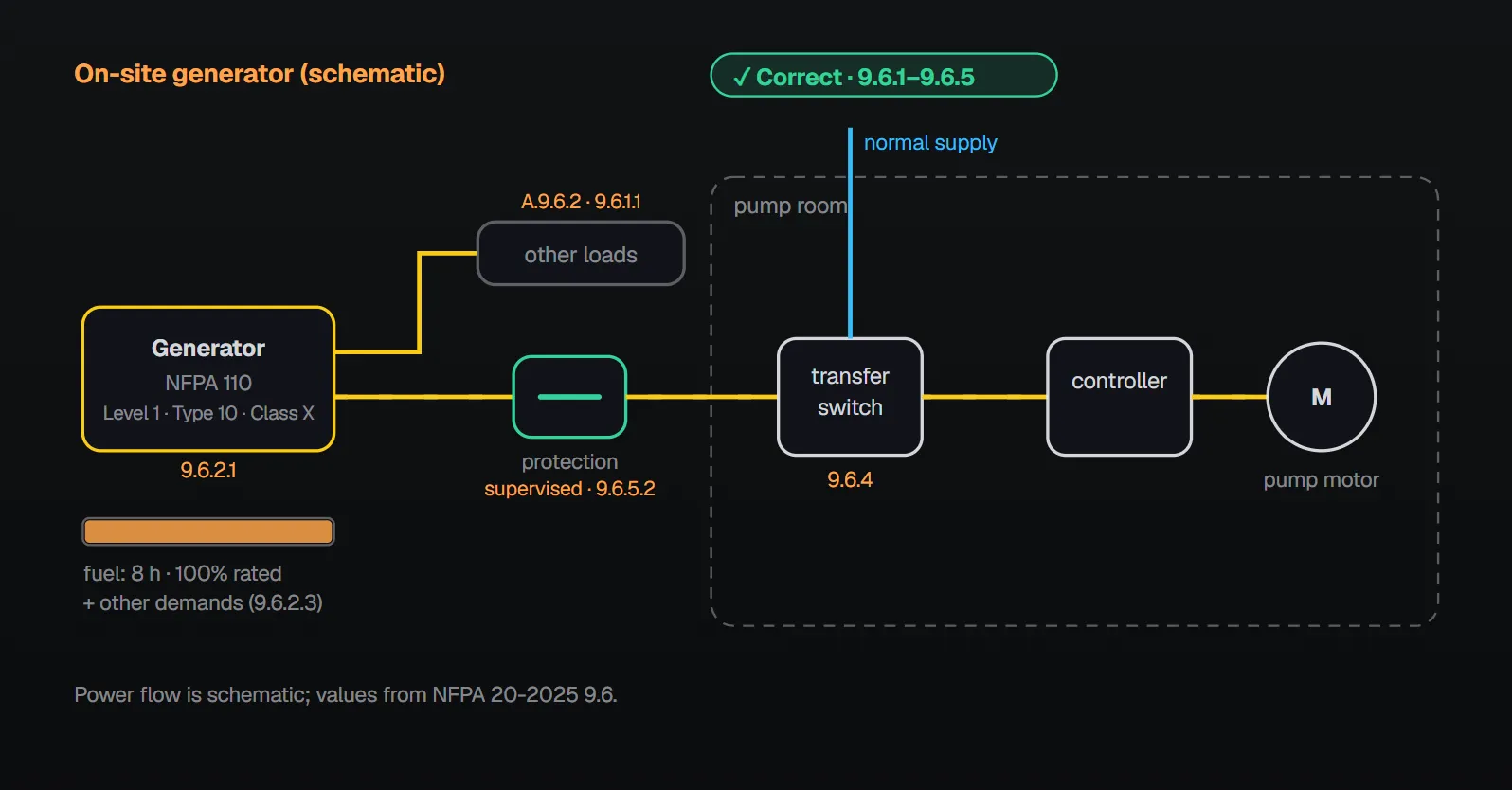
In short: the generator allows normal starting and running of the fire pump motor(s) while supplying all other simultaneously operated loads and meeting Section 9.4 (9.6.1.1). It meets NFPA 110 Level 1, Type 10, Class X (9.6.2.1) and keeps producing rated nameplate power without shutdown or derate for alarms, warnings or failed engine sensors, except overspeed shutdown (9.6.2.2). Fuel covers 8 hours of pump operation at 100 percent of rated capacity plus other demands (9.6.2.3). Transfer between normal and alternate supply takes place within the pump room (9.6.4). Protective devices allow instantaneous pickup of the full pump room load and are supervised by remote monitoring (9.6.5.1, 9.6.5.2).
Capacity (9.6.1)
Where on-site generator systems supply fire pump motors to meet 9.3.2, they have sufficient capacity to allow normal starting and running of the motor(s) driving the fire pump(s) while supplying all other simultaneously operated loads and meeting Section 9.4 (9.6.1.1). A tap ahead of the on-site generator disconnecting means is not required (9.6.1.2).
NFPA 20 Handbook (2022) commentary explains that 9.6.1.1 prevents undersizing the generator under any loading condition. Automatic load shedding has not been specifically permitted in NFPA 20 since the 1999 edition, but it is not specifically prohibited either; the Handbook notes that NFPA 70 permits it (695.3(D)(1)) and recommends consulting the AHJ in any case. On the tap, the Handbook explains: the generator may supply loads other than the fire pump; the requirement for a dedicated service connection applies to the normal source, not the alternate source; and the generator main breaker is often part of the generator package, so wiring ahead of it would likely void warranties and listings. The fire pump load may therefore be connected on the load side of the generator disconnecting means.
Power source requirements (9.6.2)
- On-site standby generator systems comply with Section 9.4 and meet the requirements of Level 1, Type 10, Class X systems of NFPA 110 (9.6.2.1).
- The generator runs and continues to produce rated nameplate power without shutdown or derate for alarms and warnings or failed engine sensors, except for overspeed shutdown (9.6.2.2).
- Fuel supply capacity is sufficient for 8 hours of fire pump operation at 100 percent of the rated pump capacity in addition to the supply required for other demands (9.6.2.3).
Per Annex A.9.6.2, where a generator supplies loads in addition to one or more fire pump drivers, the fuel supply should be sized for all connected loads for the desired duration; such loads can include emergency lighting, exit signage and elevators.
Why these requirements?
According to the Handbook (2022) commentary, NFPA 110 Level 1, Type 10, Class X ensures the alternate power source is available within 10 seconds, a period considered necessary for an adequate water supply in a fire. NFPA 110 also contains requirements aimed at generator reliability, a need shown whenever gen-sets fail to start in wide-area outages. For 9.6.2.2 the Handbook says the rule gives the engine backing up an electric driver a level of performance similar to the diesel fire pump chapter (Chapter 11). The need for 8 hours of operation, the Handbook adds, has been demonstrated many times by long-lasting fires, especially in high-rise buildings.
Sequencing and transfer of power (9.6.3, 9.6.4)
Automatic sequencing of the fire pumps is permitted in accordance with 10.5.2.5 (9.6.3); the Handbook notes that 10.5.2.5 requires sequential starting of pumps in parallel or in series. Transfer of power to the controller between the normal supply and one alternate supply takes place within the pump room (9.6.4). The Handbook reason: so the transfer switch can be operated quickly after a power failure, particularly when it is not part of the controller. The transfer switch itself is in Section 10.8; our earlier article on fire pump power supply and transfer summarizes it.
Protective devices (9.6.5)
| Rule | Section |
|---|---|
| Protective devices in the fire pump circuits of the generator source allow instantaneous pickup of the full pump room load and comply with 700.32 of NFPA 70 | 9.6.5.1 |
| Protective devices in the fire pump circuit are supervised by remote monitoring | 9.6.5.2 |
| The fire pump circuit breaker need not be coordinated with the generator protective device, provided it is used in an individual branch circuit and is coordinated with all other line side protective devices | 9.6.5.3 |
Per Annex A.9.6.5, generator protective devices are sized to allow instantaneous pickup of the full pump room load, including starting any and all connected fire pumps across the line (full voltage). This is always the case when a pump is started with the emergency-run mechanical control (10.5.3.2).
The Handbook (2022) commentary gives the reason: 9.6.5 prevents nuisance tripping of the generator protective device when the transfer switch connects the full pump room load. The controller’s circuit breaker should be the only device that disconnects the motor under any loading other than short circuit; if an upstream device opens, it may be impossible to reset or replace it quickly enough to return the pump to service. When the fire service uses the emergency-run operator, the motor starts at full voltage, and the protective devices must not trip on locked rotor current. For 9.6.5.2: an open breaker or blown fuse prevents connecting the motor to its source; a monitoring device reports its position to a normally attended location. For 9.6.5.3: selective coordination is not needed between two devices in series when no loads are connected in parallel with the downstream device.
What to watch on site
The standard gives no list of errors for this section; the points below follow only from the text and the Annex A / Handbook reasons:
- Sizing fuel for the pump alone: 9.6.2.3 adds other demands, and Annex A.9.6.2 names all connected loads.
- Sizing the generator without the simultaneously operated loads (9.6.1.1).
- A generator protective device that trips on pump starting: 9.6.5.1 requires instantaneous pickup of the full load.
- An unsupervised breaker or fuse (9.6.5.2).
- Transfer outside the pump room (9.6.4).
Checklist
- Can the generator start and run the pump motors together with the other simultaneous loads while Section 9.4 is met? (9.6.1.1)
- Does the system meet NFPA 110 Level 1, Type 10, Class X? (9.6.2.1)
- Is shutdown or derate on alarms and sensor failures limited to overspeed? (9.6.2.2)
- Is there fuel for 8 hours at 100 percent rated capacity plus other demands? (9.6.2.3)
- Is transfer within the pump room? (9.6.4)
- Do protective devices pick up the full load instantaneously, comply with 700.32 and have remote supervision? (9.6.5.1, 9.6.5.2)
Frequently Asked Questions
How much fuel must a fire pump generator have?
Enough for 8 hours of fire pump operation at 100 percent of rated pump capacity in addition to the supply required for other demands (9.6.2.3). Annex A.9.6.2 recommends sizing fuel for all connected loads where the generator supplies other loads.
Which NFPA 110 class must the generator meet?
Level 1, Type 10, Class X, and Section 9.4 as well (9.6.2.1). Per the Handbook (2022) commentary, this makes the alternate source available within 10 seconds.
Can the generator shut itself down on a fault alarm?
No. It keeps producing rated nameplate power without shutdown or derate for alarms, warnings or failed engine sensors; the only exception is overspeed shutdown (9.6.2.2).
Where must the transfer switch be?
Transfer of power to the controller between the normal and alternate supply takes place within the pump room (9.6.4). The Handbook reason is quick operation after a power failure.
May the generator output breaker trip when the pump starts?
It must not. Protective devices allow instantaneous pickup of the full pump room load (9.6.5.1); per Annex A.9.6.5 this includes across-the-line starting of all connected pumps. The devices are supervised by remote monitoring (9.6.5.2).

SprinkCalc — Fire Sprinkler Design Across Three Standards
SprinkCalc covers hazard classification, design density and area, K-factor selection, water demand and hydraulic calculations for NFPA 13, FM Global and BS EN 12845 in a single iOS app, and exports a professional PDF report.
Download SprinkCalc on the App Store
MEP Calc — 110+ Engineering Calculators
MEP Calc bundles 110+ engineering modules in one iOS app: 21 fire calculations plus heating, cooling, HVAC, plumbing, steam and natural gas.
Download MEP Calc on the App StoreNFPA 20-2025, Standard for the Installation of Stationary Pumps for Fire Protection: 9.6.1.1, 9.6.1.2; 9.6.2.1–9.6.2.3; 9.6.3; 9.6.4; 9.6.5.1–9.6.5.3; Annex A.9.6.2, A.9.6.5 (explanatory). NFPA 20 Handbook 2022 commentary: 9.6.1.1, 9.6.1.2, 9.6.2.1, 9.6.2.2, 9.6.2.3, 9.6.3, 9.6.4, 9.6.5, 9.6.5.2 and 9.6.5.3.