The fire pump controller starts the pump on a drop in system pressure. The small pipe that carries that pressure to the controller is the pressure sensing line. NFPA 20-2025 Section 4.32 spells out where the line is taken from, what it is made of, how it is dampened and how it is tested. This article summarises the rules with their paragraph numbers and gives the reasons only from the standard’s Annex A and the NFPA 20 Handbook (2022) commentary.
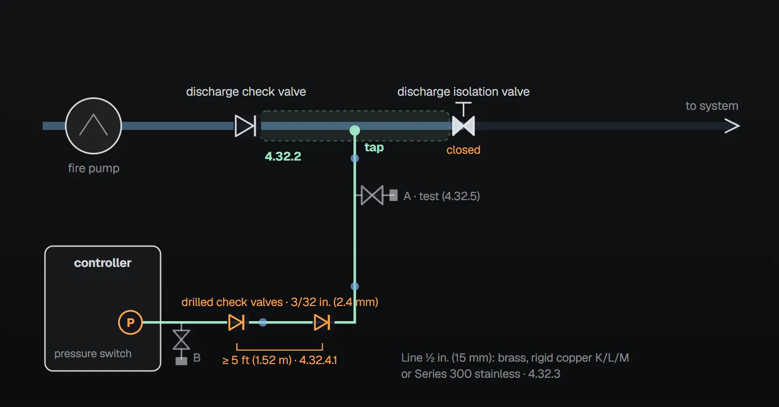
In short: every controller, jockey pumps included, has its own sensing line (4.32.1). The connection is made between that pump’s discharge check valve and discharge isolation valve (4.32.2). The line is brass, rigid copper Type K, L or M, or Series 300 stainless steel, ½ in. (15 mm) nominal (4.32.3). It carries two check valves at least 5 ft (1.52 m) apart with a 3/32 in. (2.4 mm) hole in the clapper; with clean water, drilled-diaphragm ground-face unions may replace them (4.32.4). Two test valve assemblies are provided (4.32.5) and there is no shutoff valve in the line (4.32.6).
What the rule says
| Topic | Rule | Paragraph |
|---|---|---|
| Own line | Every controller, jockey pumps included, has its own individual line. | 4.32.1 |
| Multistage multiport pump | An individual line to the fire pump controller for each discharge port; the jockey pump controller also has an individual line for each discharge port. | 4.32.1.1, 4.32.1.1.1 |
| Connection point | Between the pump’s discharge check valve and discharge isolation valve. | 4.32.2 |
| Material and size | Brass, rigid copper pipe Type K, L or M, or Series 300 stainless steel pipe or tube; fittings ½ in. (15 mm) nominal. | 4.32.3 |
| Dampening | Two bronze or stainless steel check valves at least 5 ft (1.52 m) apart, with a 3/32 in. (2.4 mm) hole in the bronze or stainless clapper. | 4.32.4.1 |
| Clean-water option | Ground-face unions with noncorrosive diaphragms drilled with a 3/32 in. (2.4 mm) orifice in place of the check valves. | 4.32.4.2 |
| Test valves | Two inspection test valves: a tee, a valve, a second tee with the branch plugged, and a second valve. | 4.32.5 |
| Shutoff valve | No shutoff valve in the line. | 4.32.6 |
| Starting | Pressure switch actuation at the low setting starts the pump starting sequence if the pump is not already running. | 4.32.7 |
The jockey pump sensing line also follows Section 4.32 (4.27.6.6).
At the controller
- Water piping is not extended into the controller (10.5.2.1.1.2); Annex A.10.5.2.1.1.2 notes that piping and associated devices can be attached to the outside of the controller.
- No pressure snubber or restrictive orifice within the sensing device (10.5.2.1.2), and no valve or other restriction as part of the controller ahead of it (10.5.2.1.4).
- Provision is made for relieving pressure to the sensing device to test the controller and pumping unit (10.5.2.1.7; 12.7.2.1.7 for diesel controllers).
- A pressure-recording device records the pressure in each controller sensing line at the controller input (10.5.2.1.8.2).
- The diesel controller clauses repeat that there is no shutoff valve in the sensing line (12.7.2.1.8).
Figure A.4.32: test connections
Figure A.4.32(a) shows the piping for each automatic pressure switch on electric and diesel fire pumps and jockey pumps: the line is taken from a tapped outlet between the indicating control valve and the check valve, and ½ in. (15 mm) globe valves with ¼ in. (6 mm) plugs give a test connection at A or B. Per the figure notes, on engine-driven pumps the solenoid drain valve can be at A, at B or inside the controller enclosure, and if water pulsation makes the switch or recorder erratic a supplemental air chamber or pulsation damper might be needed. Figure A.4.32(b) draws the fire pump and jockey pump lines of a diesel installation separately, each with check valves at least 5 ft (1.5 m) apart.
Why?
- Connection point. Annex A.10.5.2.1 says that connecting the line between the discharge check valve and the control valve makes it possible to isolate the jockey pump controller and line for maintenance without draining the whole system. The NFPA 20 Handbook (2022) commentary gives two reasons: the pump can be tested and its pressure settings verified with the system isolated, and the line can be serviced without draining the entire system.
- Own line. Per the Handbook (2022), separate lines add reliability to starting and control: if one line becomes obstructed, the other is not affected. The Handbook shows combined lines as an installation that does not comply with 4.32.1.
- Drilled check valves. The Handbook (2022) says they absorb the pressure surge created when the fire pump starts; without them the pressure switch inside the controller could be damaged. They are installed as in Figure A.4.32(a): restricting flow from the pump to the controller and opening on flow from the controller to the pump.
- Rigid material. Annex A.4.32.3: soft copper tubing is not permitted because it is easily damaged. The same annex notes that pipe sizes follow approximate inside diameter and tube sizes outside diameter: ½ in. (15 mm) pipe corresponds to ⅝ in. (16 mm) or 0.625 in. (15 mm) O.D. tube.
- Electronic sensor check. Per Annex A.10.5.2.1.3.1, when the solenoid drain valve opens the restricting orifice in the sensing line keeps the transducer pressure near zero, and that is when the transducer can be verified to read below 10 psi. If the reading exceeds the higher of 10 psi (0.68 bar) or 3.33 percent of the controller’s maximum rated pressure during such an automatic start, the controller gives an audible and visual signal (10.5.2.1.3.1).
- No shutoff valve. Neither the standard nor the Handbook gives a separate reason; the rule is absolute (4.32.6).
Arrangements that break the rule
- Combining the fire pump and jockey pump lines into one pipe: the Handbook (2022) shows this as non-compliant with 4.32.1.
- Taking the connection on the system side of the discharge isolation valve: contrary to 4.32.2, and the two benefits listed by the Handbook are lost.
- Fitting a shutoff valve in the line (4.32.6, 12.7.2.1.8).
- Using soft copper tubing (A.4.32.3).
- Extending water piping into the controller (10.5.2.1.1.2).
Checklist
- Does every controller, jockey included, have its own line? (4.32.1)
- On a multiport pump, is there a separate line per discharge port? (4.32.1.1)
- Is the connection between the discharge check valve and the discharge isolation valve? (4.32.2)
- Is the line brass, rigid copper K/L/M or Series 300 stainless, ½ in. (15 mm)? (4.32.3)
- Are the two drilled check valves at least 5 ft (1.52 m) apart with a 3/32 in. (2.4 mm) hole, or drilled-diaphragm unions where water is clean? (4.32.4)
- Are there two tee–valve–plugged tee–valve test assemblies? (4.32.5)
- Is there no shutoff valve in the line? (4.32.6)
- Does the water piping stay outside the controller? (10.5.2.1.1.2)
For verifying the pressure settings at start-up see the commissioning pressure settings article; for the controller’s overall functions see the fire pump controller article.
Frequently Asked Questions
Can the fire pump and the jockey pump share one sensing line?
No. Under NFPA 20-2025 4.32.1 every controller, jockey pumps included, has its own line. The NFPA 20 Handbook (2022) notes that separate lines add reliability: if one becomes obstructed, the other is not affected.
Where is the sensing line connected?
Between the pump’s discharge check valve and discharge isolation valve (4.32.2). Annex A.10.5.2.1 says this lets the controller and line be isolated for maintenance without draining the whole system; the Handbook (2022) adds that the pump can be tested and its settings verified with the system isolated.
Why does the line have drilled check valves?
4.32.4.1 requires two check valves at least 5 ft (1.52 m) apart with a 3/32 in. (2.4 mm) hole in the clapper. Per the Handbook (2022) they absorb the pressure surge when the pump starts; without them the pressure switch inside the controller could be damaged. With clean water, drilled-diaphragm ground-face unions may be used (4.32.4.2).
Can a shutoff valve be fitted in the sensing line for maintenance?
No. There is no shutoff valve in the line (4.32.6; 12.7.2.1.8 for diesel controllers). Testing uses the two tee–valve–plugged tee–valve assemblies (4.32.5).
Is soft copper tubing allowed for the sensing line?
No. Annex A.4.32.3 says soft copper is not permitted because it is easily damaged. The line is brass, rigid copper Type K, L or M, or Series 300 stainless steel, ½ in. (15 mm) (4.32.3).

SprinkCalc — Fire Sprinkler Design Across Three Standards
SprinkCalc covers hazard classification, design density and area, K-factor selection, water demand and hydraulic calculations for NFPA 13, FM Global and BS EN 12845 in a single iOS app, and exports a professional PDF report.
Download SprinkCalc on the App Store
MEP Calc — 110+ Engineering Calculators
MEP Calc bundles 110+ engineering modules in one iOS app: 21 fire calculations plus heating, cooling, HVAC, plumbing, steam and natural gas.
Download MEP Calc on the App StoreNFPA 20-2025, Standard for the Installation of Stationary Pumps for Fire Protection: 4.27.6.6; 4.32.1–4.32.7; 10.5.2.1.1.2, 10.5.2.1.2, 10.5.2.1.3.1, 10.5.2.1.4, 10.5.2.1.7, 10.5.2.1.8.2; 12.7.2.1.7, 12.7.2.1.8; Figures A.4.32(a), A.4.32(b); Annex A.4.32.3, A.10.5.2.1, A.10.5.2.1.1.2, A.10.5.2.1.3.1 (explanatory). NFPA 20 Handbook 2022 commentary: Section 4.32.