Every fire pump goes through an acceptance test when it is installed and through flow tests for the rest of its life. That needs a test arrangement: a test header with hose valves, a flowmeter, or both. NFPA 20-2025 sets out what the arrangement must be able to measure and how meters and hose valves are selected in Section 4.22, and gives the minimum pipe and device sizes in the Section 4.28 tables.
In short: the installation is arranged so the pump can be tested at its rated conditions and the suction supply at the maximum flow available from the pump (4.22.1.1). Metering devices or fixed nozzles are listed and capable of at least 175% of rated pump capacity (4.22.2.1, 4.22.2.2). Hose valves are listed; their number and size come from Section 4.28 (4.22.3.1.1, 4.22.3.1.2). A test header is installed on an exterior wall or elsewhere outside the pump room where water can be discharged (4.22.1.5). A meter in a loop arrangement needs an alternate means of measuring flow (4.22.2.10).
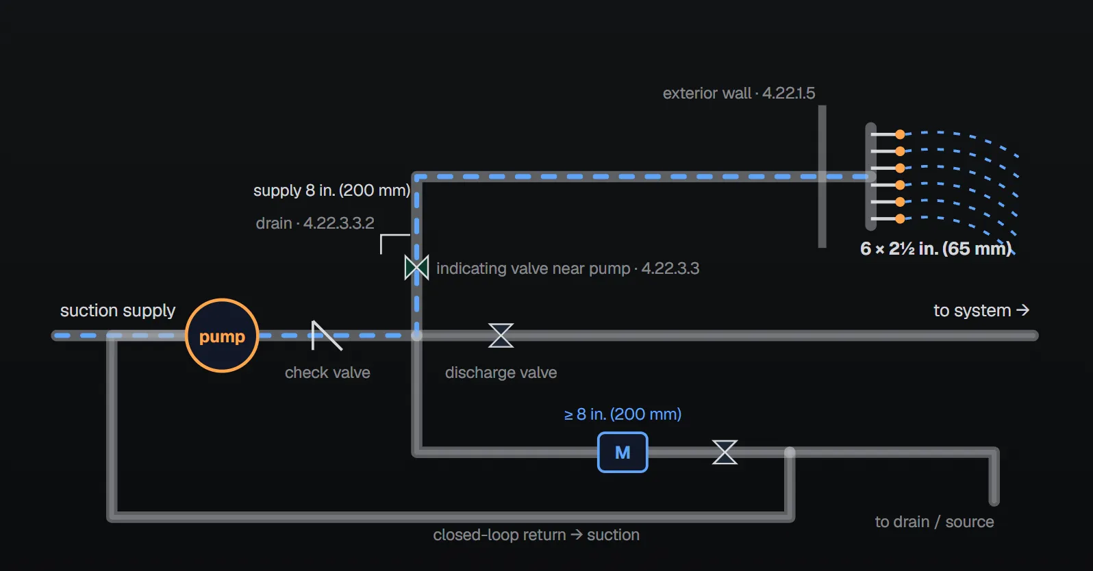
What must the test prove?
Per Annex A.4.22.1.1 a pump test has two objectives: to show that the pump itself still works properly and that the water supply can still deliver the correct amount of water to the pump at the correct pressure. Some arrangements do not test the supply, so every installation needs at least one arrangement that does. The same annex notes that NFPA 25 requires the pump test at least once every 3 years by a method that tests the supply.
Annex A.4.22.1.3 (note 5) states that a closed-loop meter arrangement tests only net pump performance, not the suction supply, valves or piping. The NFPA 20 Handbook (2022) commentary distinguishes three methods: test header, a meter discharging to the supply or another acceptable point, and closed loop. Because the closed loop does not test the supply’s ability to get water to the pump, it cannot be used for the acceptance test; acceptance testing runs the pump at 100% and 150% without recirculating to the suction.
Flowmeter
- Listed (4.22.2.1) and capable of at least 175% of rated pump capacity (4.22.2.2). The standard gives no separate reason for 175%.
- Meter piping may be sized hydraulically but not smaller than the meter manufacturer specifies (4.22.2.3). If not sized hydraulically, all meter piping follows the manufacturer but is not smaller than the meter device sizes in Section 4.28 (4.22.2.4).
- For non-hydraulically sized piping not exceeding 100 ft (30.5 m) equivalent length, the minimum meter size for the pump may be used (4.22.2.5). Above 100 ft (30.5 m), including straight pipe, fitting equivalents, elevation and meter loss, the next larger pipe size is used (4.22.2.6).
- The primary element suits the pipe size and pump rating; the readout instrument is sized for the pump’s rated capacity (4.22.2.7, 4.22.2.8).
- When test water returns to a tank, the outlet is placed far enough from the suction that the pump cannot draft air brought in by it (4.22.2.9). Annex A.4.22.2.1 recommends discharging to drain, or back to the source (suction tank, small pond) where the supply is limited; entering below minimum water level is not likely to create an air problem.
- A meter in a loop arrangement needs an alternate means of measuring flow, located downstream of and in series with the meter and working over the full test range; a properly sized test header is acceptable (4.22.2.10–4.22.2.10.3). Annex A.4.22.2.10 adds that it also verifies the meter’s accuracy.
Multiple pumps
Test discharge piping may be manifolded to a common measuring device and discharge (4.22.1.2). Where one pump can supply the maximum demand, or pumps are in series, the common piping, device and discharge are sized for the pump with the highest rated flow; where parallel pumps must run together, for their combined rated flow (4.22.1.2.1–4.22.1.2.3). The common device must measure accurately for one pump and for all pumps running together (4.22.1.2.4), and each pump’s test connection has a control valve upstream of the manifold (4.22.1.2.5). The Handbook (2022) commentary suggests two meters in parallel in that case, one sized for 150% of a single pump and one for 150% of all simultaneous pumps, because the larger meter is not accurate enough at a single pump’s lower flow.
Test header and hose valves
- Hose valves are listed; number and size come from Section 4.28 (4.22.3.1.1, 4.22.3.1.2).
- Where outlets are used for testing, either hose valves on a header supplied per 4.22.3.4 and Section 4.28, or wall hydrants, yard hydrants or standpipe outlets of sufficient number and size (4.22.3.1.3).
- Hose valves have the NH standard external thread per NFPA 1960; where local fire department connections differ and the connection serves as a wall hydrant, the authority having jurisdiction designates the threads (4.22.3.2).
- A listed indicating butterfly or gate valve is in the line to the header, at a point close to the pump (4.22.3.3.1, 4.22.3.3.3), with a drain valve or automatic ball drip at the low point between the valve and the header (4.22.3.3.2).
Annex A.4.22.1.5 explains the outdoor location: test water must go to a safe outdoor point and the pumps and controllers must be protected from accidental spray. Where theft or vandalism is a concern, the valves may be inside the building but outside the pump room if the authority having jurisdiction judges the flow can be directed outside safely. Annex A.4.22.3.1 places the connection between the discharge check valve and the discharge gate valve, with hose valves located to avoid water damage to the driver or controller; where the header also serves as a yard hydrant, the number of hose valves is not reduced below two.
Header supply pipe
Pipe size follows one of three methods (4.22.3.4):
- Where the pipe between the header and the connection to the pump discharge pipe is over 15 ft (4.5 m) long, use the next larger size than Section 4.28.
- Where that pipe has more than four fittings that change direction, use the next larger size as well.
- Size it by hydraulic calculation matching the actual test configuration, including the required pitot pressure, friction loss in pipe and fire hose, equivalent lengths of fittings, control valve and hose valves, and elevation loss from the pump discharge flange to the outlets.
The installation is proven by a test flowing the lesser of 150% of rated flow or the maximum flow available at the lowest permissible suction pressure and achieving the required pitot pressure or higher (4.22.3.4.1). The Handbook (2022) commentary notes that loss in direction-changing fittings can match that of long pipe; Figure A.4.22.3.4(3) in Annex A gives a sample header calculation for a 1500 gpm pump.
Table 4.28: minimum pipe and device sizes
The sizes in Tables 4.28(a) and 4.28(b) are minimums (4.28). Both tables are combined below: each cell gives the inch value from the US table first and the metric table’s mm value in parentheses.
| Pump rating gpm (L/min) | Suctiona,b,c | Dischargea | Main relief valve | Main relief valve discharge | Meter device | Hose valves number — size | Nonthreaded connections number — size | Hose header supply |
|---|---|---|---|---|---|---|---|---|
| 25 (95) | 1 (25) | 1 (25) | ¾ (19) | 1 (25) | 1¼ (32) | 1 — 1½ (1 — 38) | 1 — 2½ (1 — 65) | 1 (25) |
| 50 (189) | 1½ (38) | 1¼ (32) | 1¼ (32) | 1½ (38) | 2 (50) | 1 — 1½ (1 — 38) | 1 — 2½ (1 — 65) | 1½ (38) |
| 100 (379) | 2 (50) | 2 (50) | 1½ (38) | 2 (50) | 2½ (65) | 1 — 2½ (1 — 65) | 1 — 2½ (1 — 65) | 2½ (65) |
| 150 (568) | 2½ (65) | 2½ (65) | 2 (50) | 2½ (65) | 3 (75) | 1 — 2½ (1 — 65) | 1 — 2½ (1 — 65) | 2½ (65) |
| 200 (757) | 3 (75) | 3 (75) | 2 (50) | 2½ (65) | 3 (75) | 1 — 2½ (1 — 65) | 1 — 2½ (1 — 65) | 2½ (65) |
| 250 (946) | 3½ (85) | 3 (75) | 2 (50) | 2½ (65) | 3½ (85) | 1 — 2½ (1 — 65) | 1 — 2½ (1 — 65) | 3 (75) |
| 300 (1,136) | 4 (100) | 4 (100) | 2½ (65) | 3½ (85) | 3½ (85) | 1 — 2½ (1 — 65) | 1 — 2½ (1 — 65) | 3 (75) |
| 400 (1,514) | 4 (100) | 4 (100) | 3 (75) | 5 (125) | 4 (100) | 2 — 2½ (2 — 65) | 1 — 5 (1 — 125) | 4 (100) |
| 450 (1,703) | 5 (125) | 5 (125) | 3 (75) | 5 (125) | 4 (100) | 2 — 2½ (2 — 65) | 1 — 5 (1 — 125) | 4 (100) |
| 500 (1,892) | 5 (125) | 5 (125) | 3 (75) | 5 (125) | 5 (125) | 2 — 2½ (2 — 65) | 1 — 5 (1 — 125) | 4 (100) |
| 750 (2,839) | 6 (150) | 6 (150) | 4 (100) | 6 (150) | 5 (125) | 3 — 2½ (3 — 65) | 1 — 5 (1 — 125) | 6 (150) |
| 1,000 (3,785) | 8 (200) | 6 (150) | 4 (100) | 8 (200) | 6 (150) | 4 — 2½ (4 — 65) | 1 — 5 (1 — 125) | 6 (150) |
| 1,250 (4,731) | 8 (200) | 8 (200) | 6 (150) | 8 (200) | 6 (150) | 6 — 2½ (6 — 65) | 1 — 5 (1 — 125) | 8 (200) |
| 1,500 (5,677) | 8 (200) | 8 (200) | 6 (150) | 8 (200) | 8 (200) | 6 — 2½ (6 — 65) | 1 — 5 (1 — 125) | 8 (200) |
| 2,000 (7,570) | 10 (250) | 10 (250) | 6 (150) | 10 (250) | 8 (200) | 6 — 2½ (6 — 65) | 2 — 5d (2 — 125d) | 8 (200) |
| 2,500 (9,462) | 10 (250) | 10 (250) | 6 (150) | 10 (250) | 8 (200) | 8 — 2½ (8 — 65) | 2 — 5d (2 — 125d) | 10 (250) |
| 3,000 (11,355) | 12 (300) | 12 (300) | 8 (200) | 12 (300) | 8 (200) | 12 — 2½ (12 — 65) | 2 — 5d (2 — 125d) | 10 (250) |
| 3,500 (13,247) | 12 (300) | 12 (300) | 8 (200) | 12 (300) | 10 (250) | 12 — 2½ (12 — 65) | 3 — 5d (3 — 125d) | 12 (300) |
| 4,000 (15,140) | 14 (350) | 12 (300) | 8 (200) | 14 (350) | 10 (250) | 16 — 2½ (16 — 65) | 3 — 5d (3 — 125d) | 12 (300) |
| 4,500 (17,032) | 16 (400) | 14 (350) | 8 (200) | 14 (350) | 10 (250) | 16 — 2½ (16 — 65) | 3 — 5d (3 — 125d) | 12 (300) |
| 5,000 (18,925) | 16 (400) | 14 (350) | 8 (200) | 14 (350) | 10 (250) | 20 — 2½ (20 — 65) | 3 — 5d (3 — 125d) | 12 (300) |
Table notes: (1) The main relief valve is permitted to be sized per 4.20.2.1. (2) The main relief valve discharge is permitted to be sized per 4.20.6.2. (3) The flowmeter device is permitted to be sized per 4.22.2.3. (4) The hose header supply is permitted to be sized per 4.22.3.4. (5) Other types of test outlets are permitted where approved; in the US table this note also covers other sizes and quantities. a: Actual pump flange diameter may differ from pipe diameter. b: Applies only to the portion of suction pipe specified in 4.16.3.3. c: Suction sizes are based on a maximum velocity at 150% rated capacity of 15 ft/sec (4.6 m/sec) in most cases. d: Provide a control valve on each outlet where more than one nonthreaded connection is required.
Common field mistakes
- Closed loop only: it does not test the supply, valves or piping (A.4.22.1.3 note 5); the Handbook (2022) says the acceptance test then cannot be completed.
- Prolonged recirculation: damaging heat builds up unless some water is wasted (A.4.22.1.3 note 8).
- Inverted “U” piping: traps air and needs automatic air release; return piping must not carry air to the impeller eye (notes 3 and 6).
- Side connection of the return to the suction: turbulence causes cavitation and is not recommended; for horizontal split-case pumps keep at least 10 suction pipe diameters to the suction flange (notes 7 and 2).
- Returning test water to a tank near the suction: the pump can draft air (4.22.2.9).
- Leaving the flowmeter open: Annex A.4.26 lists “flowmeter left on, bypassing the pump” among conditions for which a signal might be recommended.
- Not draining the header after a test: the Handbook (2022) notes freezing can damage the header and hose valves.
Checklist
- At least one arrangement tests the pump and the suction supply together (4.22.1.1, A.4.22.1.1).
- Meter or fixed nozzle listed and capable of at least 175% (4.22.2.1, 4.22.2.2).
- Meter and pipe not smaller than Table 4.28; next larger pipe above 100 ft (30.5 m) equivalent (4.22.2.4–4.22.2.6).
- Alternate measuring means downstream of and in series with a loop meter (4.22.2.10.1).
- Hose valves listed, number and size per Table 4.28, NH thread or as the authority designates (4.22.3.1, 4.22.3.2).
- Indicating valve close to the pump and a drain at the low point of the header line (4.22.3.3).
- Header supply one size up above 15 ft (4.5 m) or more than four direction changes, or hydraulically calculated, and proven by test (4.22.3.4, 4.22.3.4.1).
- Header on an exterior wall or outside the pump room (4.22.1.5).
Frequently Asked Questions
What flow is the flowmeter sized for?
A listed meter or fixed nozzle must be capable of at least 175% of rated pump capacity (NFPA 20-2025 4.22.2.1, 4.22.2.2). Meter and piping are not smaller than Table 4.28; above 100 ft (30.5 m) equivalent length the next larger pipe size is used (4.22.2.4–4.22.2.6).
Is a closed-loop meter enough?
Not on its own. A closed loop tests net pump performance only, not the suction supply (A.4.22.1.3 note 5). Every installation needs at least one arrangement that tests the supply (A.4.22.1.1), and a loop meter needs an alternate measuring means downstream of and in series with it (4.22.2.10).
How many hose valves does a 1500 gpm pump need?
Per Table 4.28, six 2½ in. (65 mm) hose valves; meter device at least 8 in. (200 mm) and hose header supply 8 in. (200 mm). If the supply pipe is over 15 ft (4.5 m) or has more than four direction-changing fittings, use the next larger size (4.22.3.4).
Can the test header be inside the pump room?
The rule calls for an exterior wall or another location outside the pump room that allows discharge (4.22.1.5). Per Annex A.4.22.1.5, where theft or vandalism is a concern the valves may be inside the building but outside the pump room if the authority having jurisdiction agrees.
Can several pumps share one flowmeter?
Yes (4.22.1.2). Common piping and device are sized for the combined rated flow of parallel pumps that must run together, otherwise for the pump with the highest rated flow; each pump’s test connection has a control valve upstream of the manifold (4.22.1.2.1–4.22.1.2.5).

SprinkCalc — Fire Sprinkler Design Across Three Standards
SprinkCalc covers hazard classification, design density and area, K-factor selection, water demand and hydraulic calculations for NFPA 13, FM Global and BS EN 12845 in a single iOS app, and exports a professional PDF report.
Download SprinkCalc on the App Store
MEP Calc — 110+ Engineering Calculators
MEP Calc bundles 110+ engineering modules in one iOS app: 21 fire calculations plus heating, cooling, HVAC, plumbing, steam and natural gas.
Download MEP Calc on the App StoreNFPA 20-2025, Standard for the Installation of Stationary Pumps for Fire Protection: 4.22.1.1, 4.22.1.2–4.22.1.2.5, 4.22.1.5; 4.22.2.1–4.22.2.10.3; 4.22.3.1.1–4.22.3.4.1; 4.28, Tables 4.28(a), 4.28(b); Annex A.4.22.1.1, A.4.22.1.3, A.4.22.1.5, A.4.22.2.1, A.4.22.2.10, A.4.22.3.1, A.4.26, Figure A.4.22.3.4(3) (explanatory). NFPA 20 Handbook 2022 commentary: Section 4.22.