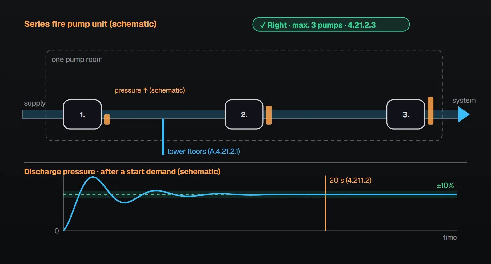
In a series arrangement one pump takes suction from another pump’s discharge. NFPA 20-2025 defines this as a “series fire pump unit” and sets performance, arrangement, signal and communication rules for the whole unit in Section 4.21.
In short: a series fire pump unit performs to the standard as an entire unit and is field acceptance tested (4.21.1.1, 4.21.1.3). Within 20 seconds after a demand to start it supplies a stable discharge pressure (±10 percent), and restabilizes within 20 seconds whenever the flow changes (4.21.1.2, 4.21.1.2.1). No more than three pumps, of which no more than two variable speed (4.21.2.3, 4.21.2.4). The pumps are in the same room; separate rooms are permitted under five conditions (4.21.2.1, 4.21.2.2). No automatic shutdown for suction pressure, and no pressure-reducing, pressure-regulating or butterfly valves between the pumps (4.21.2.5, 4.21.2.6, 4.17.9).
What is a series fire pump unit?
A series fire pump unit is all fire pump units in the same building operating in series, where the first pump takes suction directly from a water supply and each sequential pump takes suction under pressure from the preceding pump. Two pumps operating in series through a tank or break tank are not a series unit (3.3.58). Per A.3.3.58, pumps that fill tanks are not in series with the pumps supplied by those tanks; utility or campus pumps feeding a building’s fire pump are outside the definition, but their arrangement should be reviewed when evaluating the water supply. The suction pipe of a subsequent pump begins at the system side of the discharge valve of the previous pump (4.16.1.2).
Performance (4.21.1)
- The unit (pumps, drivers, controllers and accessories) performs in compliance with the standard as an entire unit (4.21.1.1).
- Within 20 seconds after a demand to start, the pumps supply and maintain a stable discharge pressure (±10 percent) over the entire range of operation (4.21.1.2); the pressure restabilizes within 20 seconds whenever the flow condition changes (4.21.1.2.1).
- The complete unit is field acceptance tested (4.21.1.3, Section 14.2).
Per the NFPA 20 Handbook (2022) commentary, pressure and flow oscillations can occur when one pump takes suction from another, especially with variable speed pumps; 20 seconds was found to be an achievable time for stable operation. Excessive oscillation can damage the pumps and be a problem for a firefighter using a hose stream.
Arrangement rules (4.21.2)
| Rule | Clause | Handbook (2022) reasoning |
|---|---|---|
| All pumps of the unit in the same pump room (except per 4.21.2.2) | 4.21.2.1 | Separate rooms can cause operational issues such as starting and stopping in the proper sequence |
| No more than three pumps in series | 4.21.2.3 | Failure of an upstream pump fails all downstream pumps; reliability drops, pressure and complexity rise |
| No more than two variable speed pumps in series | 4.21.2.4 | All adjust speed at once, making set pressure harder to hold; oscillation can occur |
| No pump shut down automatically for any suction pressure condition | 4.21.2.5 | — |
| No pressure-reducing or pressure-regulating valves between the pumps | 4.21.2.6 | — |
| With all pumps at shutoff and rated speed at maximum static suction supply, pressure at any point does not exceed any pump suction, discharge or case working pressure rating | 4.21.2.7 | — |
| No butterfly valve between pumps | 4.17.9 | OS&Y gate valves as suction and discharge valves of the lead pump(s) |
Per Annex A.4.21.2.1, with series pumps in the same room the discharge pressure of the second (or third) pump is typically too high for sprinkler or standpipe outlets on the lower floors; rather than use pressure-reducing valves, it is a common and accepted practice to take the fire protection supply from the discharge of the preceding pump through a connection between that pump and the subsequent pump(s).
Separate pump rooms
The pumps may be in separate rooms where all of the following are met (4.21.2.2):
- All pumps operating in series can be manually stopped or started from every room housing them.
- Suction and discharge pressures of all pumps are displayed in every room.
- Alarms and signals are annunciated in the other rooms per 4.21.2.8 and 4.21.2.9.
- Interconnect control wiring between controllers in different rooms complies with 4.21.2.8 and 4.21.2.9.
- A pump room communication system complies with 4.21.2.9 and 4.21.2.10.
Per the Handbook (2022) commentary, these conditions allow vertical staging of pumps; it can eliminate express risers but might add a test riser, and it needs primary and standby power to the upper pump(s) and protected control wiring between the pumps.
Control wiring
Interconnected control wiring of series pumps not in the same room that affects starting of the supply (lower zone) pump(s) is protected against fire and physical damage like the power conductors of NFPA 70 Article 695 (4.21.2.8.1). Annex A.4.21.2.8.1 lists acceptable methods: encased in at least 2 in. (50 mm) of concrete; a listed fire-rated assembly of at least 2 hours dedicated to the fire pump circuit(s); a listed electrical circuit protective system of at least 2 hours; or a listed 2-hour assembly containing only emergency alarm and/or control circuits for fire pumps, emergency systems generators or legally required generators, with no power circuits. The lower zone motor starts on the opening of the control circuit (remote start) loop (4.21.2.8.1.1); controllers meet 10.5.2.5 or 12.7.2.5 (4.21.2.8.1.2).
Status signals and communication
| Electric series pump (4.21.2.9.1.1) | Diesel series pump (4.21.2.9.1.2) |
|---|---|
| Pump running (10.4.7.2.1) | Pump running (12.4.2.3(1)) |
| Phase loss (10.4.7.2.2) | Control switch in off or manual (12.4.2.3(2)) |
| Phase reversal (10.4.7.2.3) | Trouble on controller or engine (12.4.2.3(3)) |
| Controller connected to alternative source (10.4.7.2.4) | Low suction pressure |
| Alternate circuit breaker open or tripped (10.8.3.12.1) | |
| Low suction pressure |
Each room has audible and visual signals for the series pumps not located in it (4.21.2.9.1). Low suction pressure means suction pressure more than 10 psi (0.68 bar) below the design suction pressure on any downstream series pump. Controllers have additional contacts for remote indication, not required where other means communicate the information (4.21.2.9.2, 4.21.2.9.2.1). Where the pumps are not in the same room, each room has a two-way in-building emergency services communications system per NFPA 72 that meets its survivability requirements (4.21.2.10.1, 4.21.2.10.1.1). The Handbook (2022) notes that running pump rooms are noisy and normal means of communication are often unsatisfactory during testing and emergencies.
Common field mistakes
- A fourth pump, or three variable speed pumps: contrary to 4.21.2.3 and 4.21.2.4.
- Pressure-reducing or butterfly valve between pumps: prohibited by 4.21.2.6 and 4.17.9.
- Low suction pressure shutdown: 4.21.2.5 does not permit automatic shutdown.
- Rating components for one pump only: 4.21.2.7 checks all pumps at shutoff with maximum static suction.
- Unprotected control wiring or no communication system between rooms: contrary to 4.21.2.8.1 and 4.21.2.10.1.
Checklist
- Does the arrangement fall under 3.3.58, or is there a break tank between the pumps?
- No more than three pumps, no more than two variable speed (4.21.2.3, 4.21.2.4).
- Stable pressure within ±10 percent in 20 seconds shown in the acceptance test (4.21.1.2, 4.21.1.3).
- No pressure-reducing, pressure-regulating or butterfly valve between pumps (4.21.2.6, 4.17.9).
- Pressure at every point below ratings at shutoff with maximum static suction (4.21.2.7).
- Separate rooms: five conditions, protected wiring, signals and communication in place (4.21.2.2, 4.21.2.8–4.21.2.10).
Frequently Asked Questions
Are two pumps working through a break tank in series?
No. Per NFPA 20-2025 3.3.58, two pumps that operate in series through a tank or break tank are not a series fire pump unit; per A.3.3.58, pumps that fill tanks are not in series with the pumps supplied by those tanks.
How many pumps can be arranged in series?
No more than three (4.21.2.3), and no more than two of them variable speed (4.21.2.4). Per the Handbook (2022), each added pump lowers reliability because an upstream failure also stops the downstream pumps.
How fast must series pumps reach stable pressure?
Within 20 seconds after a demand to start, a stable discharge pressure (±10 percent) over the entire range of operation; after any change in flow, the pressure restabilizes within 20 seconds (4.21.1.2, 4.21.1.2.1).
Can series pumps be on different floors?
Yes, if all five conditions are met (4.21.2.2): manual start and stop from every room, suction and discharge pressures of all pumps displayed in every room, alarm and signal annunciation, protected control wiring and an NFPA 72 communication system.
How do I reduce pressure for the lower floors?
No pressure-reducing or pressure-regulating valves go between the pumps (4.21.2.6). Annex A.4.21.2.1 describes taking the lower-floor supply from the preceding pump’s discharge, through a connection between that pump and the next, as common and accepted practice.

SprinkCalc — Fire Sprinkler Design Across Three Standards
SprinkCalc covers hazard classification, design density and area, K-factor selection, water demand and hydraulic calculations for NFPA 13, FM Global and BS EN 12845 in a single iOS app, and exports a professional PDF report.
Download SprinkCalc on the App Store
MEP Calc — 110+ Engineering Calculators
MEP Calc bundles 110+ engineering modules in one iOS app: 21 fire calculations plus heating, cooling, HVAC, plumbing, steam and natural gas.
Download MEP Calc on the App StoreNFPA 20-2025, Standard for the Installation of Stationary Pumps for Fire Protection: 3.3.58; 4.16.1.2; 4.17.9; 4.21.1.1–4.21.2.10.1.1; Annex A.3.3.58, A.4.21.2.1, A.4.21.2.8.1 (explanatory). NFPA 20 Handbook 2022 commentary: Sections 4.17.8 and 4.21.