A variable speed fire pump limits system pressure by changing speed. NFPA 20-2025 defines two kinds of variable speed pump: a pump with a variable speed pressure limiting control and a self-regulating variable speed fire pump unit (3.3.79.4). This article covers the second one, Section 4.8.
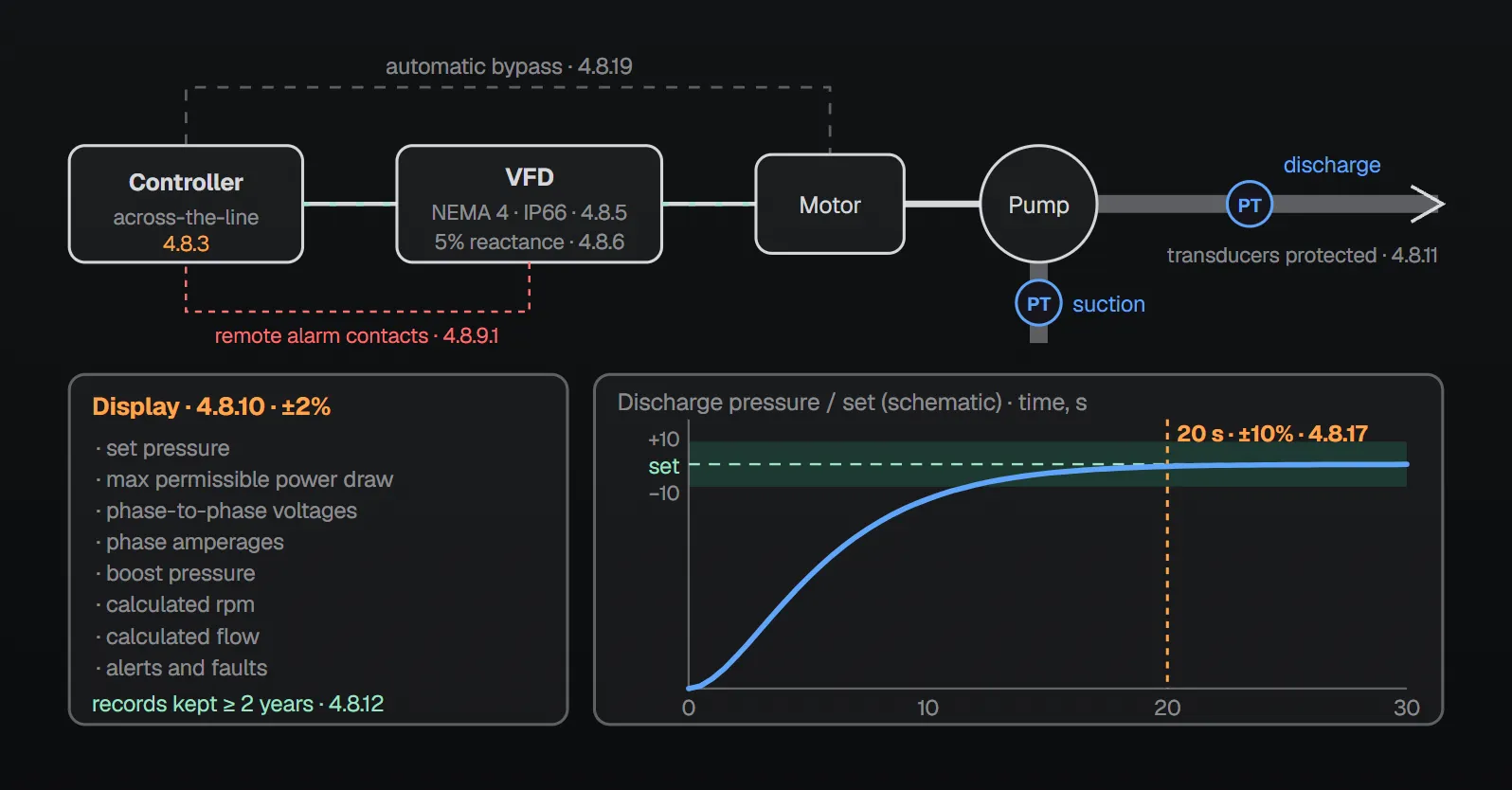
In short: the unit is factory assembled and listed as a unit (4.8.2) and is provided with an across-the-line fire pump controller in accordance with Chapter 10 (4.8.3). The drive control unit is in at least a NEMA Type 4, IP66 enclosure (4.8.5) with at least 5 percent line reactance on the input (4.8.6). The unit monitors suction and discharge pressure, power draw and calculated flow and sends a supervisory alarm when they do not match its design curve (4.8.8), and reports ten drive conditions as well (4.8.9). Within 20 seconds after a demand to start the discharge pressure is stable within ±10 percent (4.8.17); at no flow it runs at a speed giving at least 25 percent of rated pressure (4.8.16).
What is the unit?
By definition a self-regulating variable speed fire pump unit is a factory-built integrated unit of centrifugal pump, driver and variable speed control unit. It maintains the set pressure until the maximum pump brake horsepower is reached, acting as a variable speed pressure limiting control and/or a variable speed suction limiting control (3.3.79.2). The part that controls pump speed and power is the self-regulating control (3.3.79.1).
Annex A.3.3.79.2 explains that the factory-embedded logic knows the suction pressure, discharge pressure and power draw, calculates flow and net pressures from them and communicates that information. All accessories needed to limit discharge and net pressure by speed regulation are integrated in the unit. The same annex recommends that each unit include a bypass that operates in automatic mode and via a manual mechanical operator, bypassing the VFD to apply power directly to the motor.
What the rules say
Unit, test data and controller
- Each self-regulating control unit maintains the factory-certified test data for variable speed operating conditions (4.8.1).
- The unit is factory assembled and listed as a unit (4.8.2).
- It is provided with an across-the-line fire pump controller in accordance with Chapter 10 (4.8.3). Where alternate power is provided, an across-the-line combination fire pump controller/transfer switch is required (4.8.4).
- Motor-starting contactors comply with 10.4.5.1 (4.8.18). An automatic bypass per 10.10.3 and 10.10.4.2 (4.8.19), an emergency-run mechanical control per 10.5.3.2 (4.8.20) and circuit protection in the VFD path per 10.10.5 (4.8.21) are provided. Local control follows 10.10.7.1 and 10.10.7.3 (4.8.23).
- The assembly is marked with its short-circuit current rating (4.8.22).
Electrical limits
- The drive control unit is in at least a NEMA Type 4 watertight enclosure with an IP66 rating (4.8.5).
- At least 5 percent line reactance is provided on the input (4.8.6).
- The VFD output current rating marked on the controller nameplate is not exceeded when the motor runs at the maximum pump horsepower of 4.11.3 (4.8.7).
- The maximum operating frequency does not exceed line frequency (4.8.24).
Monitoring, alarms and records
- Suction pressure, discharge pressure, power draw and calculated flow are monitored; a supervisory alarm goes to the controller whenever the results do not match the design curve of the unit (4.8.8).
- The variable speed drive is monitored and a supervisory alarm goes to the controller for any of these conditions (4.8.9): (1) pump run, (2) high temperature, (3) overcurrent, (4) overvoltage, (5) undervoltage, (6) ground fault, (7) phase loss, (8) set pressure not met, (9) overpressure, (10) bypass mode. Remote contacts that close on alarm are provided for connection to the controller (4.8.9.1).
- Annex A.4.8.9(8): the “set pressure not met” signal is sent whenever discharge pressure is below the set pressure and power draw is below the design maximum.
- A visible display shows at least the set pressure, maximum permissible power draw, all phase-to-phase voltages, all phase amperages, boost pressure, calculated rpm, calculated flow, alerts and faults, with an accuracy within ±2 percent (4.8.10).
- Suction and discharge transducers are provided and protected from mechanical damage (4.8.11).
- All operating information is captured and kept for at least 2 years (4.8.12).
Installation and operation
- A minimum clear working space per 110.26(A)(1) of NFPA 70 is provided for the pump, variable speed driver and self-regulating control unit (4.8.13).
- The unit has no resonant first-order harmonic critical speed below 120 percent of maximum operating speed in self-regulating or manual operator mode, whichever is greater (4.8.14).
- The set pressure can be field adjusted (4.8.15); the adjustment is secured by password or equivalent means (4.8.15.1).
- At no flow the unit operates at a speed that provides at least 25 percent of its rated pressure (4.8.16).
- Within 20 seconds after a demand to start, the pump supplies and maintains a stable discharge pressure (±10 percent) throughout the entire range of operation (4.8.17).
Rules for the unit elsewhere in the standard
- Shop test: two additional certified curves per pump, one at constant discharge pressure and one at constant boost pressure, from churn to beyond 150 percent of rated flow until maximum brake horsepower is reached (4.5.1.5). See fire pump unit performance and shop test.
- Below rated speed in self-regulating mode, discharge pressure is held within 5 percent of the set pressure (6.2.2.2).
- Where the unit is applied to the output of the controller, the controller meters need not keep their accuracy; the meters on the unit are used (10.3.4.3.1).
- At acceptance the installed unit equals the performance in the manufacturer’s certified self-regulating mode shop test data within the accuracy limits of the test equipment (14.2.4.2.3).
- Variable speed pumps are acceptable to limit system pressure; set pressure plus the maximum pressure variance during variable speed operation, adjusted for elevation, does not exceed the rating of any component (4.7.7.3.1, 4.7.7.3.2). See pump, driver and controller compatibility.
- With an electric variable speed pump an additional circulation relief valve or temperature-actuated relief valve is permitted (4.13.6); see circulation relief valve.
Why?
The standard gives no separate reason for most 4.8 clauses, and the NFPA 20 Handbook (2022) adds no commentary to them. The explanations found in the sources are:
- No-flow speed: The Annex A note to 4.8.16 says that at no flow the jockey pump might keep system pressure above the set pressure, slowing the variable speed control; this limits the minimum pump speed to approximately 50 percent of rated speed.
- Why variable speed: in the Handbook (2022) commentary on 4.7.7.3.1, a variable speed pump limits pressure by speed in systems where pressure at low flow can exceed component ratings, such as ESFR sprinkler and standpipe systems, and can remove the need for pressure-reducing valves in some designs. In its example a standpipe system demanding 1000 gpm (3785 L/min) at 150 psi (10.3 bar) needs a pump rated 1000 gpm at 160 psi (11 bar), assuming 0 psi at the suction flange; that pump can produce as much as 224 psi (15.5 bar), well above the 175 psi (12.1 bar) component rating. A variable speed pump with a 165 psi (11.4 bar) set pressure meets the demand without overpressurizing the system.
Checklist
- Unit listed as a unit, factory-certified variable speed test data available (4.8.1, 4.8.2, 4.5.1.5).
- Across-the-line controller; with alternate power, a combination controller/transfer switch (4.8.3, 4.8.4).
- Enclosure at least NEMA Type 4 / IP66; at least 5% input reactance; short-circuit current rating marked (4.8.5, 4.8.6, 4.8.22).
- Automatic bypass, emergency-run mechanical control and VFD-path circuit protection present (4.8.19–4.8.21).
- The ten VFD alarms and the design-curve alarm reach the controller through remote contacts (4.8.8, 4.8.9, 4.8.9.1).
- Transducers protected; records kept at least 2 years (4.8.11, 4.8.12).
- Set pressure adjustment secured by password or equivalent (4.8.15.1).
- At acceptance, ±10% stability within 20 seconds and at least 25% of rated pressure at no flow confirmed (4.8.16, 4.8.17).
Frequently Asked Questions
What is a self-regulating variable speed fire pump unit?
A factory-built integrated unit of centrifugal pump, driver and variable speed control unit that maintains the set pressure until the maximum pump brake horsepower is reached (NFPA 20-2025 3.3.79.2). It is factory assembled and listed as a unit (4.8.2).
Which controller does the unit use?
An across-the-line fire pump controller in accordance with Chapter 10 (4.8.3). Where alternate power is provided, an across-the-line combination controller/transfer switch is required (4.8.4); an automatic bypass is provided per 10.10.3 and 10.10.4.2 (4.8.19).
Which conditions does the VFD alarm?
Pump run, high temperature, overcurrent, overvoltage, undervoltage, ground fault, phase loss, set pressure not met, overpressure and bypass mode each send a supervisory alarm to the controller (4.8.9). A further alarm is sent when the measurements do not match the design curve (4.8.8).
How slow can the unit run at no flow?
It operates at a speed that provides at least 25 percent of its rated pressure (4.8.16). The Annex A note to 4.8.16 says that when the jockey pump keeps pressure above the set pressure the control slows down, limiting minimum speed to approximately 50 percent of rated speed.
How quickly must pressure settle after start?
Within 20 seconds after a demand to start the pump supplies and maintains a stable discharge pressure within ±10 percent throughout its range (4.8.17). Below rated speed in self-regulating mode the discharge pressure stays within 5 percent of the set pressure (6.2.2.2).

SprinkCalc — Fire Sprinkler Design Across Three Standards
SprinkCalc covers hazard classification, design density and area, K-factor selection, water demand and hydraulic calculations for NFPA 13, FM Global and BS EN 12845 in a single iOS app, and exports a professional PDF report.
Download SprinkCalc on the App Store
MEP Calc — 110+ Engineering Calculators
MEP Calc bundles 110+ engineering modules in one iOS app: 21 fire calculations plus heating, cooling, HVAC, plumbing, steam and natural gas.
Download MEP Calc on the App StoreNFPA 20-2025, Standard for the Installation of Stationary Pumps for Fire Protection: 3.3.79.1, 3.3.79.2, 3.3.79.4; 4.8.1–4.8.24; 4.5.1.5; 4.7.7.3.1, 4.7.7.3.2; 4.13.6; 6.2.2.2; 10.3.4.3.1; 14.2.4.2.3; Annex A.3.3.79.2, A.4.8.9(8) and the Annex A note to 4.8.16 (explanatory). NFPA 20 Handbook 2022 commentary: 4.7.7.3.1 (variable speed pump example).