The discharge side of a fire pump carries churn (shutoff) pressure, stops backflow and isolates the pump from the system. NFPA 20-2025 gives the general rules for all piping in the pump room in Section 4.15 and the discharge-specific rules in Section 4.17. For the suction side see suction pipe: elbows and reducers.
In short: discharge components are the pipe, valves and fittings from the pump discharge flange to the system side of the discharge valve (4.17.1). Their pressure rating must be adequate for the maximum total discharge head with the pump at shutoff and rated speed, and not less than the rating of the fire protection system (4.17.3). Above ground, steel pipe with flanges, screwed joints or mechanical grooved joints is used (4.17.4); nonmetallic flexible connection fittings are not permitted in the discharge (4.17.1.1). The discharge assembly has a listed check valve or backflow preventer, with a listed indicating gate or butterfly valve on its system side (4.17.7, 4.17.8). No pressure-regulating device goes in the discharge pipe except as the standard permits (4.17.11).
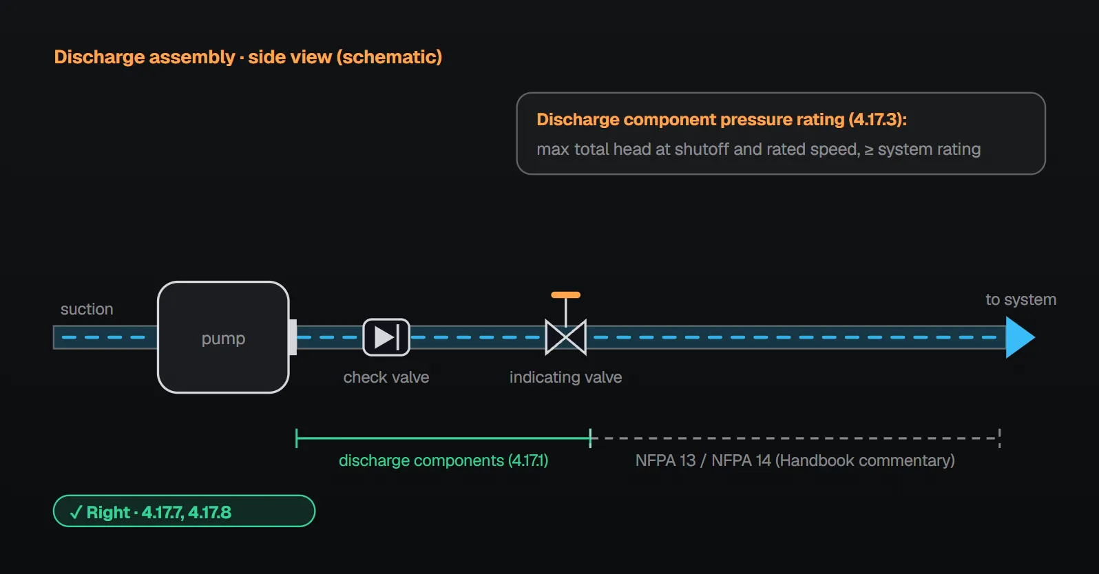
Where the discharge assembly ends
Discharge components are the pipe, valves and fittings extending from the pump discharge flange to the system side of the discharge valve (4.17.1). For multistage multiport pumps the same definition applies to each port, from that port’s discharge flange to that port’s discharge valve (4.17.2). Per the NFPA 20 Handbook (2022) commentary, piping downstream of the discharge valve is outside the scope of NFPA 20 and is designed to the standard of the system it supplies, such as NFPA 13 or NFPA 14.
All piping in the pump room (4.15)
| Item | Rule | Clause |
|---|---|---|
| Pipe material | Steel pipe above ground, except for connection to underground suction and discharge piping | 4.15.1.1 |
| Corrosive water | Steel suction pipe galvanized, or painted inside before installation with a paint recommended for submerged surfaces | 4.15.1.2 |
| Linings | No thick bituminous linings | 4.15.1.3 |
| Joining | Screwed, flanged, welded, mechanical or grooved joints, or other approved fittings | 4.15.2.1 |
| Slip-type fittings | Where installed per 4.16.6 and the piping is mechanically secured against slippage | 4.15.2.2 |
| Restricting orifices | Check valves per 4.32.4.1, orifice unions, orifice plates, flowmeters: means for internal inspection or disassembly; permanent tag | 4.15.2.3, 4.15.3 |
| Foam concentrate and additive piping | Material that will not corrode in this service; no galvanized pipe | 4.15.4.1, 4.15.4.2 |
| Drains to atmosphere | Metallic or polymeric materials permitted | 4.15.5 |
| Hangers and seismic | Support per NFPA 13 Chapter 17; seismic protection, where applicable, per NFPA 13 Chapter 18 | 4.15.6.1, 4.15.6.2 |
| Cutting and welding | Torch cutting or welding in the pump house permitted when done per NFPA 51B | 4.15.7 |
Annex A.4.15.1 recommends keeping the exterior of aboveground steel piping painted. The Handbook (2022) commentary notes that flanged fittings provide rigidity and are encouraged, especially in the suction, that grooved fittings might need more restraint, and that plastic (PVC, CPVC), fiberglass and polyethylene fittings are not permitted in the suction or discharge piping. Per the same commentary, restricting orifices are inspected periodically for corrosion and clogging, and foam concentrate can make galvanizing flake off.
Annex A.4.15.6 notes that NFPA 13 does not currently address fire pumps, controllers, drivers, fuel tanks (including trim), test header piping, relief valve piping or exhaust mufflers. Per A.4.15.7, when welding on suction or discharge piping with the pump in place, the welding ground should be on the same side of the pump as the welding; the standard gives no reason.
Discharge pipe (4.17.1.1–4.17.6)
- Pressure rating: adequate for the maximum total discharge head at shutoff and rated speed, and not less than the fire protection system rating (4.17.3). The Handbook (2022) commentary describes this as churn pressure at rated speed plus the suction head at the pump inlet, using the maximum foreseeable suction pressure.
- Pipe and joints: above ground, steel pipe with flanges, screwed joints or mechanical grooved joints (4.17.4). Annex A.4.17.4 prefers flanges welded to the pipe; per the Handbook (2022), threaded flanges are more prone to leakage and resulting corrosion over time, and 4.17.4 excludes plain or beveled end-locking valves and fittings from the discharge piping.
- Flexible connections: nonmetallic flexible pump connection fittings are not permitted in the discharge piping (4.17.1.1).
- Pressure test: all pump discharge pipe is hydrostatically tested per NFPA 13 (4.17.5).
- Size: pipe and fittings not smaller than Section 4.28 (4.17.6); the table is in the test header and flowmeter article. Annex A.4.17.6 recommends a size at which, with the pump(s) at 150 percent of rated capacity, discharge velocity does not exceed 20 ft/sec (6.1 m/sec).
Check valve, backflow preventer and discharge valve
A listed check valve or backflow preventer is installed in the discharge assembly (4.17.7), and a listed indicating gate or butterfly valve on the fire protection system side of the discharge check valve (4.17.8).
- Per the Handbook (2022) commentary, the check valve keeps water from flowing back into the pump; backflow on shutdown can cause pressure surges, and spring-loaded anti-slam check valves reduce them by minimizing backflow.
- Annex A.4.17.7: in large systems, backflow when the automatic control shuts the pump down can cause severe water hammer; where this is expected, a listed anti-water-hammer check valve should be installed in the discharge line. Automatically controlled pumps in tall buildings can give trouble as they shut down.
- Where a backflow preventer replaces the discharge check valve, an additional backflow preventer might be needed in the bypass. If the sensing line can be connected between the last check valve and the last control valve without altering the device or its listing, no separate discharge control valve is needed; if not, the line connects between the backflow preventer and the discharge control valve, and the backflow preventer cannot substitute for that valve because the sensing line must be isolatable (A.4.17.7, A.4.17.8).
- Per the Handbook (2022) commentary, discharge isolation valves do not affect pump operation, so approved indicating valves other than OS&Y are permitted; in series pumps, where one pump’s discharge is the next pump’s suction, OS&Y gate valves are used as both suction and discharge valves of the lead pump(s). A butterfly valve is not installed between pumps in series (4.17.9).
Pressure-regulating devices
No pressure-regulating devices are installed in the discharge pipe except as permitted in the standard (4.17.11); Annex A.4.17.11 refers to 4.7.7.2. The Handbook (2022) commentary notes that NFPA 20 stops at the discharge control valve and does not prohibit such devices downstream of it; the designer’s aim is to match the pump to the system demand. It adds that pressure-regulating devices operating in a mostly static condition reduce system reliability, that clogged strainers can stop pilot-operated valves from opening, and that devices whose seats are not exercised can fail closed.
Where the authority having jurisdiction requires positive suction pressure, a listed suction pressure regulating valve sensitive to suction pressure may be installed between the pump and the discharge check valve (4.17.10.1, 4.17.10.2); details are in fire pump minimum suction pressure.
Common field mistakes
- Nonmetallic flexible connector in the discharge: contrary to 4.17.1.1.
- Rating components for rated pressure only: 4.17.3 calls for shutoff pressure; the Handbook adds the maximum suction pressure.
- Threaded flanges: A.4.17.4 prefers welded flanges.
- Butterfly valve between series pumps: prohibited by 4.17.9.
- Trimming excess pressure in the discharge pipe: not permitted by 4.17.11.
Checklist
- Discharge components rated for shutoff pressure and not below the system rating (4.17.3).
- Steel pipe with flanged, screwed or grooved joints above ground; no nonmetallic flexible connector (4.17.4, 4.17.1.1).
- Discharge pipe hydrostatically tested and not smaller than Section 4.28 (4.17.5, 4.17.6).
- Listed check valve or backflow preventer, indicating valve on its system side (4.17.7, 4.17.8).
- No butterfly valve between series pumps; no unpermitted pressure-regulating device in the discharge (4.17.9, 4.17.11).
- Orifice fittings tagged and inspectable (4.15.2.3, 4.15.3).
Frequently Asked Questions
What pressure rating does the discharge piping need?
Discharge components must be adequate for the maximum total discharge head with the pump at shutoff (churn) and rated speed, and not less than the fire protection system rating (NFPA 20-2025 4.17.3). The NFPA 20 Handbook (2022) commentary adds the maximum foreseeable suction pressure.
Is there a velocity limit in the discharge pipe?
The mandatory rule is a minimum size: pipe and fittings not smaller than Section 4.28 (4.17.6). Annex A.4.17.6 also recommends a size at which velocity at 150 percent of rated capacity does not exceed 20 ft/sec (6.1 m/sec).
Can a backflow preventer replace the discharge check valve?
Yes; a listed check valve or backflow preventer is installed in the discharge assembly (4.17.7). Per A.4.17.7 the bypass may then need its own backflow preventer, and the sensing line connection decides whether a separate discharge control valve is needed.
Can the discharge valve be a butterfly valve?
Yes; a listed indicating gate or butterfly valve goes on the system side of the check valve (4.17.8). A butterfly valve is not installed between series pumps (4.17.9); the Handbook (2022) calls for OS&Y gate valves as suction and discharge valves of the lead pump(s).
Can a pressure-reducing valve go in the discharge pipe?
Not except as the standard permits (4.17.11). Per the Handbook (2022), NFPA 20 stops at the discharge control valve; piping beyond it follows the standard of the system supplied, and the aim is to match the pump to the demand.

SprinkCalc — Fire Sprinkler Design Across Three Standards
SprinkCalc covers hazard classification, design density and area, K-factor selection, water demand and hydraulic calculations for NFPA 13, FM Global and BS EN 12845 in a single iOS app, and exports a professional PDF report.
Download SprinkCalc on the App Store
MEP Calc — 110+ Engineering Calculators
MEP Calc bundles 110+ engineering modules in one iOS app: 21 fire calculations plus heating, cooling, HVAC, plumbing, steam and natural gas.
Download MEP Calc on the App StoreNFPA 20-2025, Standard for the Installation of Stationary Pumps for Fire Protection: 4.15.1.1–4.15.7; 4.16.1.2; 4.17.1–4.17.11; 4.7.7.2; 4.28; Annex A.4.15.1, A.4.15.6, A.4.15.7, A.4.17.4, A.4.17.6, A.4.17.7, A.4.17.8, A.4.17.11 (explanatory). NFPA 20 Handbook 2022 commentary: Sections 4.15 and 4.17.