When a fire pump takes its water from a tank placed between it and the city main, and that tank does not hold the whole fire protection demand, the tank is a break tank. NFPA 20-2025 defines the break tank but does not set its rules itself: it requires the installation to comply with NFPA 22. This article covers what NFPA 20 says, why break tanks are used, and what the NFPA 22 text extracted in the NFPA 20 Handbook (2022) requires.
In short: a break tank is a tank providing suction to a fire pump whose capacity is less than the fire protection demand (flow rate times flow duration) (3.3.9). Where one is used, the installation complies with NFPA 22 (4.33); NFPA 20-2025 references the 2023 edition of NFPA 22 (2.2). As a suction tank its outlet has a vortex-control assembly (4.16.10). At acceptance the tank refill rate is tested and recorded and the refill device is operated at least five times (14.2.6.3.5, 14.2.6.3.5.1).
What NFPA 20-2025 says
- Definition: a tank providing suction to a fire pump whose capacity is less than the fire protection demand (flow rate times flow duration) (3.3.9).
- Rule: where a break tank provides the pump suction water supply, the installation complies with NFPA 22 (4.33). The standard gives no size, refill or level rule of its own.
- Vortex: where a tank is the suction source, its discharge outlet has a vortex-control assembly in accordance with NFPA 22 (4.16.10). See suction screens and anti-vortex plate.
- Acceptance test: where suction is from a break tank, the tank refill rate is tested and recorded (14.2.6.3.5) and the refill device is operated a minimum of five times (14.2.6.3.5.1). The acceptance test form in Annex A (Figure A.14.2.6.3(a)) asks for the required break tank fill rate and whether the refill rate maintained the tank level while flowing 150 percent of rated capacity.
The origin and development notes give the history: break tank requirements were added in the 2007 edition, removed in the 2016 edition, and have since been applied in accordance with NFPA 22.
Why use a break tank?
Annex A.4.20.1.1 lists two ways to eliminate system overpressurization where the required system pressure is close to the pressure rating of the components and the supply pressure varies significantly over time: a tank between the water supply and the pump suction instead of a direct connection, or a variable speed pressure-limiting control device (for the main relief valve side of the topic see main relief valve location).
The NFPA 20 Handbook (2022) commentary adds other purposes: separating the fire pump from the city supply; an air gap, where the automatic fill valve discharges a sufficient distance above the highest liquid level, protects the city main against backflow contamination (the minimum air gap is typically set by plumbing codes); eliminating suction pressure fluctuations; and combining a reliable source that lacks volume with stored water to meet the full demand. Some municipalities do not permit a fire pump to connect directly to the water main. The commentary stresses that a break tank need not be small: any tank that does not hold the full demand is one.
What NFPA 22 requires (2018 extract in the Handbook)
Important: NFPA 20-2025 references the 2023 edition of NFPA 22 (2.2). The only NFPA 22 text available here is the 2018 edition extracted in Part III of the Handbook (2022); the values below come from it and should be checked against the NFPA 22 edition that applies to the project.
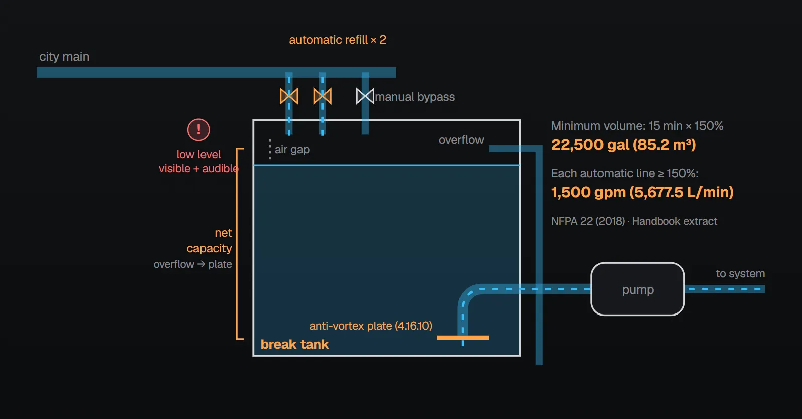
- Volume: at least 15 minutes with the fire pump operating at 150 percent of rated capacity. The commentary says this gives the fire department time to respond and verify conditions, and that it is based on the pump rating, not the fire protection demand. Example: a 1000 gpm (3785 L/min) pump flows 1500 gpm (5677 L/min) at 150 percent; 15 minutes × 1500 gpm = 22,500 gal (85 m³).
- Net capacity: for suction tanks, the volume between the inlet of the overflow and the level of the vortex plate.
- Refill mechanism: listed and arranged for automatic operation.
| Case | Automatic refill | Manual fill bypass | Other |
|---|---|---|---|
| Tank smaller than 30 minutes of maximum system demand | Dual automatic refill lines, each at least 150% of fire pump capacity; where supplies do not permit, each at least 110% of maximum system design flow | 150% of fire pump capacity; where supplies do not permit, 110% of maximum system design flow | Local visible and audible low liquid level signal near the fill mechanism (commentary: a supervisory signal to a constantly attended location is also recommended) |
| Tank holding at least 30 minutes of maximum system demand | 110% × (total demand − tank capacity) / duration | Same rate | Pipe from the city connection to the automatic fill valve per NFPA 24; fill mechanism kept at 40 °F (4.4 °C) minimum; activates no more than 4 in. (102 mm) below the overflow level |
The Handbook example: a 1000 gpm (3785 L/min) demand for 90 minutes needs 90,000 gal (340 m³). With a 45,000 gal (170 m³) tank, the other 45,000 gal must arrive in 90 minutes: 500 gpm (1892 L/min). With the 10 percent margin the refill rate is 550 gpm (2082 L/min). The commentary explains the 110 percent as an allowance for future supply degradation, and the dual automatic refill for a 15-minute tank as time for the fire department to respond and check the fill valve.
Measuring the refill rate at acceptance
The NFPA 20 Handbook (2022) commentary gives the method: lower the tank level a few inches and time how long it takes to rise again. There are 7.48 gal in 1 ft³ (1000 L in 1 m³). In a tank 40 ft, or 12.19 m, in diameter, 1 in. of water is about 783 gal and 1 cm about 1167 L. If the level rises 6 in. (15.24 cm) in 3 min 23 sec, the refill rate is about 1389 gpm. The result goes on the acceptance test form (14.2.6.3.5).
Field watch points (from the sources)
- Treating it as a full-demand tank: if capacity is below the demand it is a break tank (3.3.9) and refill is part of the supply.
- Not recording the refill rate: it must be tested and recorded at acceptance (14.2.6.3.5).
- Outlet without a plate: a vortex-control assembly is required (4.16.10).
- Clipping overpressure with the main relief valve: Annex A.4.20.1.1 points to a break tank or a variable speed pressure-limiting control instead.
Checklist
- A tank below the demand is treated as a break tank (3.3.9) and designed to NFPA 22 (4.33).
- The applicable NFPA 22 edition is identified; NFPA 20-2025 references 2023 (2.2).
- Anti-vortex plate at the tank outlet (4.16.10).
- Refill rate measured and recorded at acceptance; refill device operated at least five times (14.2.6.3.5, 14.2.6.3.5.1).
- The form records whether refill held the tank level at 150 percent of rated capacity (Figure A.14.2.6.3(a)).
Frequently Asked Questions
What is a break tank?
Per NFPA 20-2025 it is a tank providing suction to a fire pump whose capacity is less than the fire protection demand (flow rate times flow duration) (3.3.9). The Handbook (2022) notes it need not be small: any tank that does not hold the full demand is a break tank.
What does NFPA 20 require for a break tank?
Where a break tank provides the pump suction supply, the installation complies with NFPA 22 (4.33); NFPA 20-2025 references the 2023 edition (2.2). A vortex-control assembly at the outlet (4.16.10) and a recorded refill rate test at acceptance (14.2.6.3.5) are also required.
How big must a break tank be?
Per the NFPA 22 (2018) text extracted in the Handbook (2022), at least 15 minutes with the pump at 150 percent of rated capacity; for a 1000 gpm (3785 L/min) pump that is 22,500 gal (85 m³). Check the NFPA 22 edition that applies to the project.
How must a break tank be refilled?
Per the NFPA 22 (2018) extract the refill mechanism is listed and automatic. If the tank is smaller than 30 minutes of maximum demand, two automatic lines each at 150 percent of pump capacity, a manual bypass at the same rate and a local visible and audible low level signal are needed; where supplies do not permit, each line may supply 110 percent of maximum design flow.
What is done for a break tank at the acceptance test?
The refill rate is tested and recorded and the refill device is operated at least five times (14.2.6.3.5, 14.2.6.3.5.1). The Handbook (2022) suggests lowering the level a few inches and timing the rise: 6 in. in 3 min 23 sec in a 40 ft tank is about 1389 gpm.

SprinkCalc — Fire Sprinkler Design Across Three Standards
SprinkCalc covers hazard classification, design density and area, K-factor selection, water demand and hydraulic calculations for NFPA 13, FM Global and BS EN 12845 in a single iOS app, and exports a professional PDF report.
Download SprinkCalc on the App Store
MEP Calc — 110+ Engineering Calculators
MEP Calc bundles 110+ engineering modules in one iOS app: 21 fire calculations plus heating, cooling, HVAC, plumbing, steam and natural gas.
Download MEP Calc on the App StoreNFPA 20-2025, Standard for the Installation of Stationary Pumps for Fire Protection: 2.2, 3.3.9, 4.16.10, 4.33, 14.2.6.3.5, 14.2.6.3.5.1; Annex A.4.20.1.1, Figure A.14.2.6.3(a) (explanatory); origin and development (history). NFPA 20 Handbook 2022 commentary: commentary on 3.3.9 and 14.2.6.3.5; Part III Section 4, NFPA 22 (2018) extract and commentary (break tank size, refill mechanism, net capacity).