Variable speed pressure limiting control holds pump discharge pressure at the set pressure by changing motor speed; variable speed suction limiting control maintains suction pressure. NFPA 20-2025 Section 10.10 gives the rules for electric fire pump controllers equipped with these controls. The factory-built self-regulating unit is a separate topic: self-regulating variable speed fire pump.
In short: the controller is listed for fire service and complies with Chapter 10 (10.10.1.1, 10.10.1.2). It has two paths: the variable speed path and the bypass path. When the drive is not at line frequency and pressure cannot be held within 10 percent of the set pressure for more than 20 seconds, when pressure stays below the low-pressure bypass setting for more than 20 seconds, or when the drive does not indicate it is operational within 7 seconds, the controller goes to bypass and runs the pump at rated speed (10.10.3.1–10.10.3.1.2); it stays bypassed until manually restored (10.10.3.2). A line reactor of at least 5 percent impedance ahead of the drive (10.10.6.1.1), separate drive circuit protection (10.10.5.1) and a 115 percent overpressure indicator (10.10.8.3) are provided.
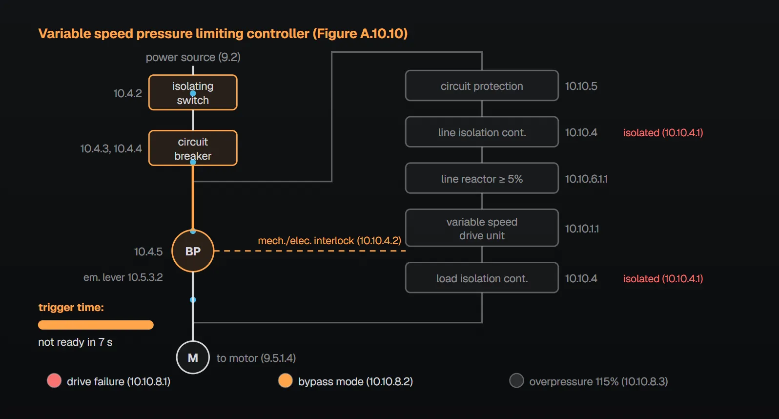
Controller layout (Figure A.10.10)
| Component | Path | Clause |
|---|---|---|
| Isolating switch and circuit breaker | Common | 10.4.2, 10.4.3, 10.4.4 |
| Bypass contactor (BP), emergency-run lever | Bypass | 10.4.5, 10.5.3.2, 10.10.3.3 |
| Separate drive circuit protection | Variable speed | 10.10.5 |
| Line isolation contactor | Variable speed | 10.10.4 |
| Line reactance | Variable speed | 10.10.6.1.1, 10.10.6.1.2 |
| Variable speed drive unit | Variable speed | 10.10.1.1 |
| Load isolation contactor (mechanically and electrically interlocked with bypass) | Variable speed | 10.10.4, 10.10.4.2 |
Per Annex A.10.10.3 the bypass path has all the characteristics of a non-variable speed fire pump controller. Per the NFPA 20 Handbook (2022) commentary these controllers are in fact two controllers: a full-service, full-speed controller (the bypass path) and a variable speed controller, both rated for continuous duty. The Handbook notes they are used where overpressurizing the piping, fittings, connection points or sprinklers could cause damage.
Basic rules (10.10.1, 10.10.2)
- The controller complies with Chapter 10, except as provided in 10.10.1 through 10.10.10 (10.10.1.1), and is listed for fire service (10.10.1.2).
- The variable speed control has a horsepower rating at least equal to the motor horsepower or, where rated in amperes, an ampere rating not less than motor full-load current (10.10.1.3). The VFD output current on the controller nameplate is not exceeded with the motor at maximum pump horsepower per 4.11.3 (10.10.1.3.1).
- Controllers and their VFD driving constant torque loads, such as positive displacement water mist or additive (foam) pumps, are rated for constant torque (10.10.1.4.1, 10.10.1.4.2).
- In addition to 10.1.2.5.1, the maximum ambient temperature rating and the VFD output current rating are marked (10.10.2). Handbook (2022): drives give off heat and shut down when their ambient rating is exceeded.
Bypass (10.10.3)
| Trigger | Time | Clause |
|---|---|---|
| Drive not at line frequency and system pressure not held within 10 percent of set pressure | More than 20 s | 10.10.3.1 |
| System pressure below the low-pressure bypass setting | More than 20 s | 10.10.3.1.1 |
| Drive does not indicate it is operational | Within 7 s | 10.10.3.1.2 |
| Manual mode selection | With a restart delay | 10.10.7.3, 10.10.3.5 |
- In bypass the controller bypasses and isolates the variable speed system and runs the pump at rated speed (10.10.3.1); higher than normal in-rush is prevented when transferring from variable speed to bypass (10.10.3.1.3).
- Once bypassed, the unit stays bypassed until manually restored (10.10.3.2); the bypass contactors are operable with the emergency-run handle of 10.5.3.2 (10.10.3.3); automatic shutdown in bypass is as permitted by 10.5.4.2 (10.10.3.4).
Annex A notes: the bypass contactor should be energized only on a pump demand to run with the control in the fault condition (A.10.10.3.1). The low-pressure bypass setting should be between the set pressure and 90 percent of system pressure at 150 percent flow, never at or below maximum expected suction pressure (A.10.10.3.1.1). If the drive fails there is no need to wait for the low-pressure bypass time (A.10.10.3.1.2). A motor running at reduced frequency connected straight to line frequency creates high transient currents that can trip the circuit breaker; back-feeding line power to the drive damages it and can trip the breaker, taking the pump out of service (A.10.10.3.1.3). The Handbook (2022) says a restart delay of 2 to 3 seconds is the most common method.
Isolation, protection and power quality
- The drive is line and load isolated when not in operation (10.10.4.1); the load isolation contactor and bypass contactor are mechanically and electrically interlocked against simultaneous closure (10.10.4.2).
- Separate drive circuit protection sits between the line side of the drive and the load side of the 10.4.3 breaker and is coordinated so the breaker does not trip on a drive fault (10.10.5.1, 10.10.5.2). Annex A.10.10.5: the intent is to keep the controller breaker from tripping on a drive failure and maintain the bypass circuit.
- Power quality correction equipment is in the variable speed circuit (10.10.6.1); a continuous-duty line reactor of at least 5 percent impedance is installed ahead of the drive (10.10.6.1.1). A reactor integral to the drive may satisfy all or part of the 5 percent if connected on the line side of the converter (rectifier) section (10.10.6.1.2).
- With higher system voltages or longer cables, cable length and motor requirements are coordinated (10.10.6.2); not required where system voltage does not exceed 480 V and motor–controller cable length does not exceed 100 ft (30.5 m) (10.10.6.3). Annex A.10.10.6.2: longer cables increase high-frequency switching voltage transients at the motor; follow the motor manufacturer’s recommended cable lengths so insulation ratings are not exceeded.
Handbook (2022) commentary: isolation separates the surge-sensitive drive from the source when not in use, extending its life and reliability. Mechanical interlocking prevents feeding drive output into the supply or the reverse; either results in damage and a tripped breaker, leaving no fire protection.
Local control and indicators
- All control devices needed to keep the controller in automatic are in lockable enclosures (10.10.7.1).
- The variable speed pressure sensing element connected per 10.5.2.1.8.6 is used only to control the drive (10.10.7.2.1); redundant elements are permitted for other functions (10.10.7.2.2).
- A means to manually select variable speed or bypass mode is provided (10.10.7.3).
- Common pressure control is not used for multiple pump installations; each controller’s sensing circuit operates independently; a water mist positive displacement pumping unit controller is the exception (10.10.7.4–10.10.7.4.2).
- Visible indicators show drive failure, bypass mode and overpressure, the last actuating at 115 percent of set pressure (10.10.8.1–10.10.8.3).
Per the Handbook (2022) common control is a single point of failure that could disable all pumps. The overpressure indicator alerts personnel; shutting down the pump is not desirable, because preventing fire spread matters more than preventing overpressure.
Performance and critical settings
- The controller has suitable adjusting means for field conditions (10.10.9.1); per Annex A.10.10.9.1 these reduce hunting, excessive overshooting or oscillating.
- Reduced-speed operation does not overheat the motor (10.10.9.2); maximum operating frequency does not exceed line frequency (10.10.9.3). Handbook (2022): no fire pump is listed above its rated speed, and pump pressure gain is proportional to the square of the speed increase.
- Within 20 seconds after a demand to start, a stable discharge pressure (±10 percent) is maintained over the entire range; after a flow change it restabilizes within 20 seconds (10.10.9.4, 10.10.9.4.1).
- A permanent means inside the enclosure records the variable speed set point, pump start pressure and pump stop pressure (10.10.10).
Variable speed on vertical pumps (10.10.11)
The pump supplier informs the controller manufacturer of all critical resonant speeds from zero to full speed; the controller avoids operating at or ramping through them and uses skip frequencies with sufficient bandwidth (10.10.11.1–10.10.11.1.2). For water-lubricated lineshaft bearings the pump manufacturer states the maximum time for water to reach the top bearing at the lowest anticipated well or reservoir level; the controller ramps up within that time, and the ramp down time is approved by the pump manufacturer (10.10.11.2–10.10.11.3). Skip frequencies and ramp times are recorded with the 10.10.10 settings (10.10.11.4, 10.10.11.5).
Common field mistakes
- Automatic return to variable speed after bypass: 10.10.3.2 requires manual restoration.
- No line reactor, or one after the drive: 10.10.6.1.1 requires at least 5 percent ahead of the drive.
- Using the speed-control sensor for other functions: contrary to 10.10.7.2.1.
- Common pressure control for several pumps: prohibited by 10.10.7.4 (except a water mist PD unit).
- Critical settings not recorded: 10.10.10 requires a permanent record.
Checklist
- Controller listed for fire service; drive rating suits the motor; ambient temperature and output current marked (10.10.1.2, 10.10.1.3, 10.10.2).
- Bypass triggers tested at 20 s, 20 s and 7 s; stays bypassed; emergency lever works (10.10.3).
- Isolation, mechanical/electrical interlock and separate circuit protection provided (10.10.4, 10.10.5).
- 5 percent line reactor; cable–motor coordination where 480 V or 100 ft (30.5 m) is exceeded (10.10.6).
- Three indicators and critical-settings record present; 20 s stability observed (10.10.8, 10.10.9.4, 10.10.10).
Frequently Asked Questions
When does a variable speed controller go to bypass?
Per NFPA 20-2025, when the drive is not at line frequency and pressure cannot be held within 10 percent of set pressure for more than 20 seconds (10.10.3.1), when pressure stays below the low-pressure bypass setting for more than 20 seconds (10.10.3.1.1), or when the drive does not indicate it is operational within 7 seconds (10.10.3.1.2). Manual selection is also provided (10.10.7.3).
Does the controller return to variable speed by itself after bypass?
No. It remains bypassed until manually restored (10.10.3.2). Per the Handbook (2022), switching back automatically would likely cause cycling and needless interruption of fire water.
How is the low-pressure bypass setting chosen?
Per Annex A.10.10.3.1.1, between the set pressure and 90 percent of system pressure with the pump at 150 percent flow, and never at or below maximum expected suction pressure.
Is a line reactor required?
Yes. A continuous-duty line reactor of at least 5 percent impedance is installed ahead of the drive (10.10.6.1.1). A reactor integral to the drive may satisfy all or part of it if connected on the line side of the rectifier (10.10.6.1.2).
Is the motor cable length limited?
No coordination is required where system voltage does not exceed 480 V and cable length does not exceed 100 ft (30.5 m) (10.10.6.3); otherwise cable length and motor requirements are coordinated (10.10.6.2). Annex A.10.10.6.2 calls for following the motor manufacturer’s recommended cable lengths.

SprinkCalc — Fire Sprinkler Design Across Three Standards
SprinkCalc covers hazard classification, design density and area, K-factor selection, water demand and hydraulic calculations for NFPA 13, FM Global and BS EN 12845 in a single iOS app, and exports a professional PDF report.
Download SprinkCalc on the App Store
MEP Calc — 110+ Engineering Calculators
MEP Calc bundles 110+ engineering modules in one iOS app: 21 fire calculations plus heating, cooling, HVAC, plumbing, steam and natural gas.
Download MEP Calc on the App StoreNFPA 20-2025, Standard for the Installation of Stationary Pumps for Fire Protection: 10.10.1.1–10.10.11.5; Annex A.10.10, A.10.10.3, A.10.10.3.1, A.10.10.3.1.1, A.10.10.3.1.2, A.10.10.3.1.3, A.10.10.5, A.10.10.6.2, A.10.10.9.1 and Figure A.10.10 (explanatory). NFPA 20 Handbook 2022 commentary: Section 10.10.