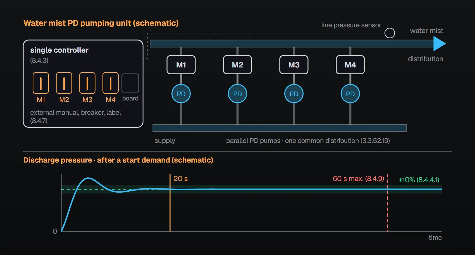
Water mist systems often use several positive displacement (PD) pumps working together on one controller instead of a single pump. NFPA 20-2025 defines this arrangement as a “water mist positive displacement pumping unit”: multiple PD pumps designed to operate in parallel that discharge into a single common water mist distribution system (3.3.52.19). The unit rules are in Section 8.4.
In short: the unit is dedicated to and listed as a unit for fire protection service; pumps, driver(s) and a single controller form a complete operating unit (8.4.1, 8.4.3). Within 20 seconds after a demand to start, the controller has the pumps supply a stable discharge pressure (±10 percent) over the entire range, and the pressure restabilizes within 20 seconds when the flow changes (8.4.4.1, 8.4.4.2). System design pressure is reached within the time in the listing, not more than 60 seconds after flow starts from the smallest nozzle, and the time is shown on a permanent sign (8.4.9, 8.4.10). Failure of the line pressure sensor or primary control board does not prevent full capacity with emergency-run mechanical control (8.4.5).
What is the unit and what does it include?
Per Annex A.3.3.52.19 the term is not meant for individual pumps supplying water mist systems. It applies to water mist systems designed with multiple pumps, where a pump operates individually or several pumps operate in parallel depending on downstream demand and the number of discharging nozzles; the pumps work together as a single unit to provide the required flow and pressure.
- The unit is dedicated to and listed as a unit for fire protection service (8.4.1).
- Except as provided in 8.4.3 through 8.4.12, all requirements of the standard apply (8.4.2).
- Pumps, driver(s) and a single controller form a complete operating unit (8.4.3); the unit has its own dedicated controller (4.7.5).
Per the NFPA 20 Handbook (2022) commentary, a dedicated controller for each driver is not required in these units, because the unit includes redundant monitoring and protection schemes so that a single point of failure does not prevent the system from performing; for NFPA 20 compliance the PD pump and the system type must be listed for fire protection use. For one driver serving several PD pumps see fire pump, driver and controller compatibility (4.7.4, 8.6.3.1). General PD pump rules are in positive displacement fire pumps; flow, NPSH and relief rules for water mist pumps are in water mist system pumps.
Performance: 20 seconds and 60 seconds
| Rule | Value | Clause |
|---|---|---|
| Controller manages all pumps; stable discharge pressure over the entire range after a demand to start | Within 20 seconds, ±10 percent | 8.4.4.1 |
| Pressure restabilizes when the flow condition changes | Within 20 seconds | 8.4.4.2 |
| System design discharge pressure after flow starts from the smallest nozzle | Time in the listing, not more than 60 seconds | 8.4.9 |
| Sign showing the time to reach design pressure | Permanently marked weatherproof metal or rigid plastic | 8.4.10 |
Per the Handbook (2022) commentary, the time limit and pressure range in 8.4.4.1 serve consistency with Chapter 10 and easier enforcement. The time to reach design pressure is evaluated in the listing and described in the manufacturer’s design manual; the 60-second maximum accommodates large systems. The sign is needed for acceptance testing and future periodic testing.
Redundancy and variable speed
Redundancy is built into the unit so that failure of a line pressure sensor or the primary control board does not prevent the system from working at full capacity with emergency-run mechanical control per 10.5.3.2 (8.4.5). That control is a handle or lever that mechanically closes the motor-circuit switching mechanism, giving nonautomatic continuous running independent of electric control circuits and the pressure switch (10.5.3.2.1, 10.5.3.2.1.1).
Where the unit has variable speed control, one of the following applies (8.4.6):
- Failure of the variable speed control feature causes the controller to bypass and isolate the variable speed control system.
- A redundant motor and pump compensate for the lost variable speed driven pump capacity.
With the second option, load isolation per 10.10.4 is not required for the variable speed pump; circuit protection per 10.10.5.1 is provided between the line side of the variable speed drive and the load side of the isolating switch; and if the isolating switch of 10.4.2 has self-protecting instantaneous short-circuit overcurrent protection, the protection of 10.10.5.2 is coordinated so the isolating switch does not trip on a drive fault (8.4.6.1). Per the Handbook (2022), the system may be overpressurized in bypass, but maintaining waterflow is more important than preventing damage to the system.
Unit controller
- Each motor can be manually operated individually without opening the enclosure door (8.4.7(1)).
- A circuit breaker per 10.4.3 and 10.4.4 is incorporated for each motor, and each breaker operator is marked to show the motor it protects (8.4.7(2), 8.4.7(3)).
- Where a single isolating switch serves all unit controllers, the requirements of 10.4.2 do not apply (8.4.7.1).
- 10.3.4.3 requires reading all line currents and voltages on the controller exterior within ±2 percent of motor nameplate values. It applies to each motor and the entire unit: where motors are fed from a common point, voltage may be monitored at that point; each line current of each motor is monitored; the total of all line currents at a common point need not be monitored (8.4.8).
Per the Handbook (2022) commentary, the NFPA 20 philosophy is to provide every opportunity to get a pump running. Without an external breaker operator, emergency personnel would have to open the single isolating switch, open the door, reset the right breaker and close the switch again, shutting down all running pumps meanwhile. Reading current and voltage from the outside verifies correct operation of each motor and the unit and limits test personnel’s exposure to electric shock and arc flash.
The phase reversal requirements in 10.4.6.2.1, 10.4.6.2.2, 10.4.7.2.3, 10.8.3.6.4 and 14.2.6.12 do not apply to PD pumps that deliver the required flow and pressure regardless of rotation direction (8.4.11). The sequential starting rules of 10.5.2.5 (for example multiple pumping units starting at intervals of 5 to 10 seconds, 10.5.2.5.3) do not apply to the starting sequence of pumps within a single unit (8.4.12).
Acceptance test
- Each pump is operated manually at least six times during the acceptance test (14.2.6.6.7).
- Each required automatic operation operates all pumps (14.2.6.6.8); with redundant pumps, each automatic operation runs the number of pumps needed for system demand and each pump operates for at least three automatic operations (14.2.6.6.9, 14.2.6.6.10).
- The automatic activation test uses a test connection simulating the smallest system nozzle in the hydraulically most remote area, discharged from maintenance or standby pressure, or a test orifice in the pump test header simulating the smallest nozzle K-factor flow; the unit reaches design pressure within the time of 8.4.9 (14.2.6.6.11.1, 14.2.6.6.11.2).
Shop test data for the unit (each independent pump, and the unit with variable speed features deactivated and activated) are covered in fire pump unit performance and shop test (4.5.1.1, 4.5.1.3, 4.5.1.4). Pressure maintenance by the unit and the single sensing line (8.5.7.2–8.5.7.4) are covered in PD pump fittings, drivers, controllers and tests.
Common field mistakes
- Calling individual pumps a “unit”: Annex A.3.3.52.19 uses the term only for multi-pump arrangements working as one unit.
- Pumps, drivers and controller not listed as a unit: contrary to 8.4.1 and 8.4.3.
- No manual operation without opening the door, or no marked breaker per motor: contrary to 8.4.7.
- No sign showing the time to design pressure: required by 8.4.10.
- Neither bypass nor redundant motor and pump on variable speed failure: contrary to 8.4.6.
Checklist
- Unit dedicated and listed as a unit; pumps, drivers and a single controller together (8.4.1, 8.4.3).
- Stable pressure within ±10 percent in 20 seconds; 20 seconds after flow changes (8.4.4.1, 8.4.4.2).
- Listed time not more than 60 seconds; sign in place (8.4.9, 8.4.10).
- Full capacity with emergency-run mechanical control on sensor or board failure (8.4.5).
- With variable speed: bypass or redundant motor and pump; protection coordination (8.4.6, 8.4.6.1).
- External manual operation, breaker and label per motor; current and voltage reading (8.4.7, 8.4.8).
- Acceptance test: six manual starts, automatic operations and smallest-nozzle test (14.2.6.6.7–14.2.6.6.11.2).
Frequently Asked Questions
Is every PD pump supplying a water mist system a “unit”?
No. Per Annex A.3.3.52.19 the term is not for individual pumps but for multi-pump arrangements where pumps run alone or in parallel depending on demand and the number of discharging nozzles, working as a single unit (3.3.52.19).
How quickly must the unit reach design pressure?
Within the time in the listing and not more than 60 seconds after flow starts from the smallest nozzle (8.4.9), shown on a permanent sign (8.4.10). In addition, a stable discharge pressure (±10 percent) is required within 20 seconds after a start demand (8.4.4.1).
Does each pump need its own controller?
No. Pumps, driver(s) and a single controller form a complete operating unit (8.4.3). Each motor, however, can be operated manually without opening the door and has its own marked circuit breaker (8.4.7).
What happens if the variable speed control fails?
Either the controller bypasses and isolates the variable speed control, or a redundant motor and pump make up the lost capacity (8.4.6). Per the Handbook (2022), bypass can overpressurize the system, but maintaining waterflow is more important.
Do phase reversal requirements apply to the unit?
Not for PD pumps that deliver the required flow and pressure regardless of rotation direction: 10.4.6.2.1, 10.4.6.2.2, 10.4.7.2.3, 10.8.3.6.4 and 14.2.6.12 do not apply (8.4.11).

SprinkCalc — Fire Sprinkler Design Across Three Standards
SprinkCalc covers hazard classification, design density and area, K-factor selection, water demand and hydraulic calculations for NFPA 13, FM Global and BS EN 12845 in a single iOS app, and exports a professional PDF report.
Download SprinkCalc on the App Store
MEP Calc — 110+ Engineering Calculators
MEP Calc bundles 110+ engineering modules in one iOS app: 21 fire calculations plus heating, cooling, HVAC, plumbing, steam and natural gas.
Download MEP Calc on the App StoreNFPA 20-2025, Standard for the Installation of Stationary Pumps for Fire Protection: 3.3.52.19; 4.5.1.1, 4.5.1.3, 4.5.1.4; 4.7.4, 4.7.5; 8.4.1–8.4.12; 10.3.4.3; 10.5.2.5.3; 10.5.3.2.1, 10.5.3.2.1.1; 14.2.6.6.7–14.2.6.6.11.2; Annex A.3.3.52.19 (explanatory). NFPA 20 Handbook 2022 commentary: Section 8.4.