The driver of a vertical turbine pump carries the full shaft and impeller thrust, allows axial impeller adjustment and, when a diesel engine drives through a right-angle gear and flexible connecting shaft, is exposed to torsional vibration. NFPA 20-2025 Section 7.5 covers the driver and 7.6 startup and maintenance. Column, strainer and foundation are in the components and installation article; driver and controller matching in the compatibility article.
In short: the driver’s thrust bearing carries the total thrust of shaft, impellers and hydraulic thrust with an average life rating of 15,000 hours (7.5.1.1) and allows axial impeller adjustment (7.5.1.2). The driver is a vertical hollow shaft motor or a vertical hollow shaft right-angle gear with a diesel engine or steam turbine; engines and turbines listed for vertical installation may use solid shafts but need a nonreverse mechanism (7.5.1.3, 7.5.1.4). With a diesel and right-angle gear, a listed torsional coupling goes on the engine side and the pump manufacturer shows with at least a 3-mass torsional frequency calculation that critical speeds are no less than 25 percent away from rated speed (7.5.1.6.1, 7.5.1.6.1.1). At startup, rotation is checked with the top coupling removed, impellers are set per the manufacturer and vibration is observed against ANSI/HI 1.4 limits (7.6.1.2–7.6.1.5).
Driver construction (7.5.1.1–7.5.1.5)
- The driver carries the total thrust of the pump, including the weight of shaft and impellers and hydraulic thrust, on a thrust bearing of ample capacity for an average life rating of 15,000 hours (7.5.1.1).
- All drivers allow axial adjustment of impellers for proper installation and operation (7.5.1.2).
- The pump is driven by a vertical hollow shaft electric motor or a vertical hollow shaft right-angle gear drive with a diesel engine or steam turbine (7.5.1.3).
- Diesel engines and steam turbines designed and listed for vertical installation with vertical turbine pumps may use solid shafts and need no right-angle gear but require a nonreverse mechanism (7.5.1.4).
- Motors are the vertical hollow-shaft type and comply with 9.5.1.9 (7.5.1.5).
Mass elastic system (7.5.1.6)
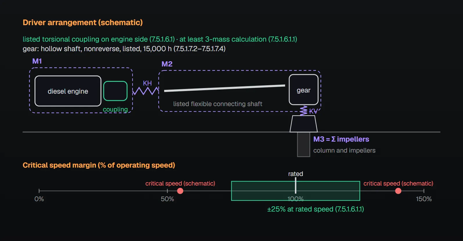
For vertical turbine pumps with right-angle gear drives driven by a diesel engine, a listed torsional coupling is used and mounted on the engine side of the driveshaft (7.5.1.6.1). For a system of diesel engine, torsional coupling, right-angle gear and vertical shaft pump, the pump manufacturer provides at minimum a 3-mass torsional frequency calculation showing that the first two natural frequencies and the critical speeds associated with engine firing frequency are no less than 25 percent above or below when the pump runs at rated speed (7.5.1.6.1.1). It includes the mass elastic characteristics of the wetted pump with its specific impeller trim, torsional coupling, right-angle gear, gear ratio, flexible connecting shaft and engine (7.5.1.6.1.2).
- Where critical speeds fall less than 25 percent from rated speed, detailed forced response calculations for the vertical and horizontal components must show no damaging vibratory stresses or torques (7.5.1.6.1.3); this analysis includes the excitation of the specific engine and rating, a fully flexible lumped parameter model along crankshaft, horizontal and vertical shafting, and the effect of engine misfire (7.5.1.6.1.4). Results also include engine critical response, crankshaft stress and crankshaft damper heat dissipation (7.5.1.6.1.7).
- With a variable speed diesel, analytical speeds run from not less than 25 percent above rated speed to not less than 25 percent below the lowest possible driver speed (7.5.1.6.1.5).
- The torsional coupling may be omitted when a complete mass elastic analysis, accepted by the authority having jurisdiction, shows the system meets 7.5.1.6.1.3 without it (7.5.1.6.1.6; similar permission in 7.5.1.6.4.1).
- For variable speed vertical hollow shaft motors, the pump manufacturer provides a complete mass elastic analysis showing no damaging stresses or critical speeds within 25 percent above and below the operating speed of pump and driver (7.5.1.6.2, 7.5.1.6.3).
Annex A.7.5.1.6.1.2 models the system as three lumped inertias connected by two springs (KH the coupling element, KV the shafting between the gear and the top impeller): M1 engine, flywheel and coupling primary; M2 coupling secondary, cardan shaft, companion flange and gear; M3 the sum of the impellers (Figure A.7.5.1.6.1.2). Per A.7.5.1.6.1, torsional couplings move harmful stresses out of the operating speed range, but a coupling with wrongly selected stiffness or damping can make torsional activity worse at operating speed. A.7.5.1.6.1.3 compares forced response results with manufacturers’ limits for each component, including vibratory torque and heat dissipation for viscoelastic elements. A.7.5.1.6.1.4 notes that emission laws have made modern engines very different, so specific engine and rating excitation data are needed. NFPA 20 Handbook (2022): a 2-mass analysis proved inadequate for this system, so the rule moved to a 3-mass analysis.
Gear drives and flexible connecting shafts (7.5.1.7, 7.5.1.8)
| Part | Rule | Clause |
|---|---|---|
| Gear and flexible shaft | Acceptable to the authority having jurisdiction | 7.5.1.7.1 |
| Gear type | Vertical hollow shaft; permits impeller adjustment | 7.5.1.7.2 |
| Reverse rotation | Nonreverse mechanism on the gear | 7.5.1.7.3 |
| Gear rating | Listed; at maximum pump horsepower and thrust for at least 15,000 hours; transfers the minimum and maximum conditions defined by the pump manufacturer | 7.5.1.7.4 |
| Water-cooled gear | Visual means to show water circulation | 7.5.1.7.5 |
| Engine connection | Except per 7.5.1.4, engine to right-angle gear through a listed flexible connecting shaft | 7.5.1.8.1 |
| Flexible shaft | Listed for diesel fire pump service; operating angle within manufacturer limits under any condition | 7.5.1.8.2, 7.5.1.8.3 |
| Listed vertical engine | Solid shaft, no right-angle drive, non-reverse ratchet required | 7.5.1.8.4 |
Handbook (2022): the flexible shaft operating angle is usually set between a minimum offset of 1 degree and a maximum of 3 degrees, to prevent failure of the universal joints.
Controllers and variable speed (7.5.2, 7.5.3)
Controllers for the motor, diesel engine or steam turbine comply with Chapter 10 (electric) or Chapter 12 (engine) (7.5.2). For a variable speed turbine pump, the pump supplier informs the controller manufacturer of all critical resonant speeds from zero to full speed (7.5.3.1). For water-lubricated pumps with lineshaft bearings, the pump manufacturer also gives the maximum allowed time for water to reach the top bearing at the lowest anticipated water level (7.5.3.2). For self-regulating variable speed see the variable speed pump article.
Startup (7.6.1)
- Before the first start after installation, all field-installed electrical connections and the discharge piping are checked (7.6.1.1).
- With the top drive coupling removed, the drive shaft is centered in the coupling for alignment and the motor is run momentarily to confirm rotation (7.6.1.2).
- With the coupling reinstalled, impellers are set for proper clearance per the manufacturer’s instructions (7.6.1.3).
- The pump is then started and run (7.6.1.4); vibration is observed against ANSI/HI 1.4 limits (7.6.1.5) and the driver is observed for proper operation (7.6.1.6).
Annex A.7.6.1.1: impeller setting should be done only by a pump manufacturer’s representative. Improper setting causes impellers to rub on pump seals, increasing friction loss and power demand; impellers set too high lose capacity, and full capacity is vital for fire pump service. The top shaft nut should be locked or pinned afterwards. Annex A.7.6.1.4: units are factory checked for smoothness; excessive vibration may come from a bent pump or column shaft, impellers not properly set, a pump not hanging freely in the well, or strain from the discharge piping. Excessive motor temperature is generally caused by sustained low supply voltage or improper impeller setting. The Handbook (2022) recommends a written report of testing and running by the installing contractor for the acceptance test report.
Maintenance (7.6.2)
Repairs, dismantling and reassembly follow the manufacturer’s instructions (7.6.2.1). Spare part orders include the pump serial number stamped on the nameplate fastened to the pump head, and for the gearbox the serial number on the gear case nameplate (7.6.2.2, 7.6.2.3). Ample head room and access for removing the pump are maintained (7.6.2.4). Handbook (2022): the serial number lets the manufacturer duplicate the listed pump’s original construction, maintaining the listing.
Common field mistakes
- Checking rotation with the coupling installed: 7.6.1.2 calls for a momentary run with the top coupling removed.
- Impeller setting without the manufacturer’s representative, or an unlocked nut: Annex A.7.6.1.1; Annex B.1.15 lists incorrect impeller adjustment as a cause of trouble.
- Diesel commissioning without torsional coupling or 3-mass calculation: required by 7.5.1.6.1 and 7.5.1.6.1.1; the coupling is omitted only with an accepted complete analysis (7.5.1.6.1.6).
- Unlisted flexible shaft or angle beyond the manufacturer limit: 7.5.1.8.2, 7.5.1.8.3.
- Critical speeds not passed to the controller manufacturer on variable speed: 7.5.3.1.
Checklist
- Thrust bearing 15,000-hour average life; impeller adjustment possible (7.5.1.1, 7.5.1.2)?
- Driver type per 7.5.1.3 or 7.5.1.4; motor vertical hollow shaft (7.5.1.5)?
- Diesel + right-angle gear: listed torsional coupling, 3-mass calculation, forced response if needed (7.5.1.6.1–7.5.1.6.1.7)?
- Gear listed, hollow shaft, nonreverse, rated 15,000 hours (7.5.1.7)?
- Flexible shaft listed, angle within manufacturer limits (7.5.1.8)?
- Startup steps and vibration record (7.6.1)?
- Serial numbers and access for removal (7.6.2)?
Frequently Asked Questions
Which drivers can a vertical turbine pump use?
Per NFPA 20-2025 7.5.1.3, a vertical hollow shaft electric motor or a vertical hollow shaft right-angle gear drive with a diesel engine or steam turbine. Engines and turbines listed for vertical installation may use solid shafts without a right-angle gear but need a nonreverse mechanism (7.5.1.4).
When is a torsional coupling required?
On diesel-driven right-angle gear turbine pumps, a listed torsional coupling is mounted on the engine side (7.5.1.6.1). It may be omitted when an accepted complete mass elastic analysis shows the system meets 7.5.1.6.1.3 without it (7.5.1.6.1.6).
What must the 3-mass torsional calculation show?
That the first two natural frequencies and the critical speeds tied to engine firing frequency are no less than 25 percent above or below the pump rated speed (7.5.1.6.1.1). If closer, detailed forced response calculations are required (7.5.1.6.1.3).
Who sets the impellers?
7.6.1.3 requires setting per the manufacturer’s instructions; Annex A.7.6.1.1 recommends that only a pump manufacturer’s representative do it and that the top shaft nut then be locked or pinned. Setting too high reduces capacity.
What is quoted when ordering spare parts?
For the pump, the serial number stamped on the nameplate on the pump head; for the gearbox, the serial number on the gear case nameplate (7.6.2.2, 7.6.2.3).

SprinkCalc — Fire Sprinkler Design Across Three Standards
SprinkCalc covers hazard classification, design density and area, K-factor selection, water demand and hydraulic calculations for NFPA 13, FM Global and BS EN 12845 in a single iOS app, and exports a professional PDF report.
Download SprinkCalc on the App Store
MEP Calc — 110+ Engineering Calculators
MEP Calc bundles 110+ engineering modules in one iOS app: 21 fire calculations plus heating, cooling, HVAC, plumbing, steam and natural gas.
Download MEP Calc on the App StoreNFPA 20-2025, Standard for the Installation of Stationary Pumps for Fire Protection: 7.5.1.1–7.5.3.2; 7.6.1.1–7.6.2.4; Annex A.7.5.1.6.1, A.7.5.1.6.1.2, A.7.5.1.6.1.3, A.7.5.1.6.1.4, Figure A.7.5.1.6.1.2, A.7.6.1.1, A.7.6.1.4 (explanatory); Annex B.1.15. NFPA 20 Handbook 2022 commentary: Sections 7.5 and 7.6.