Most of a vertical turbine pump is underground: the head and driver at grade, the column and bowls in the well or wet pit. NFPA 20-2025 Section 7.3 sets how these parts are built and which fittings attach to the pump; 7.4 covers the pump house, outdoor setting and foundation. Submergence is in the water supply and submergence article; the driver and first start in the driver and operation article.
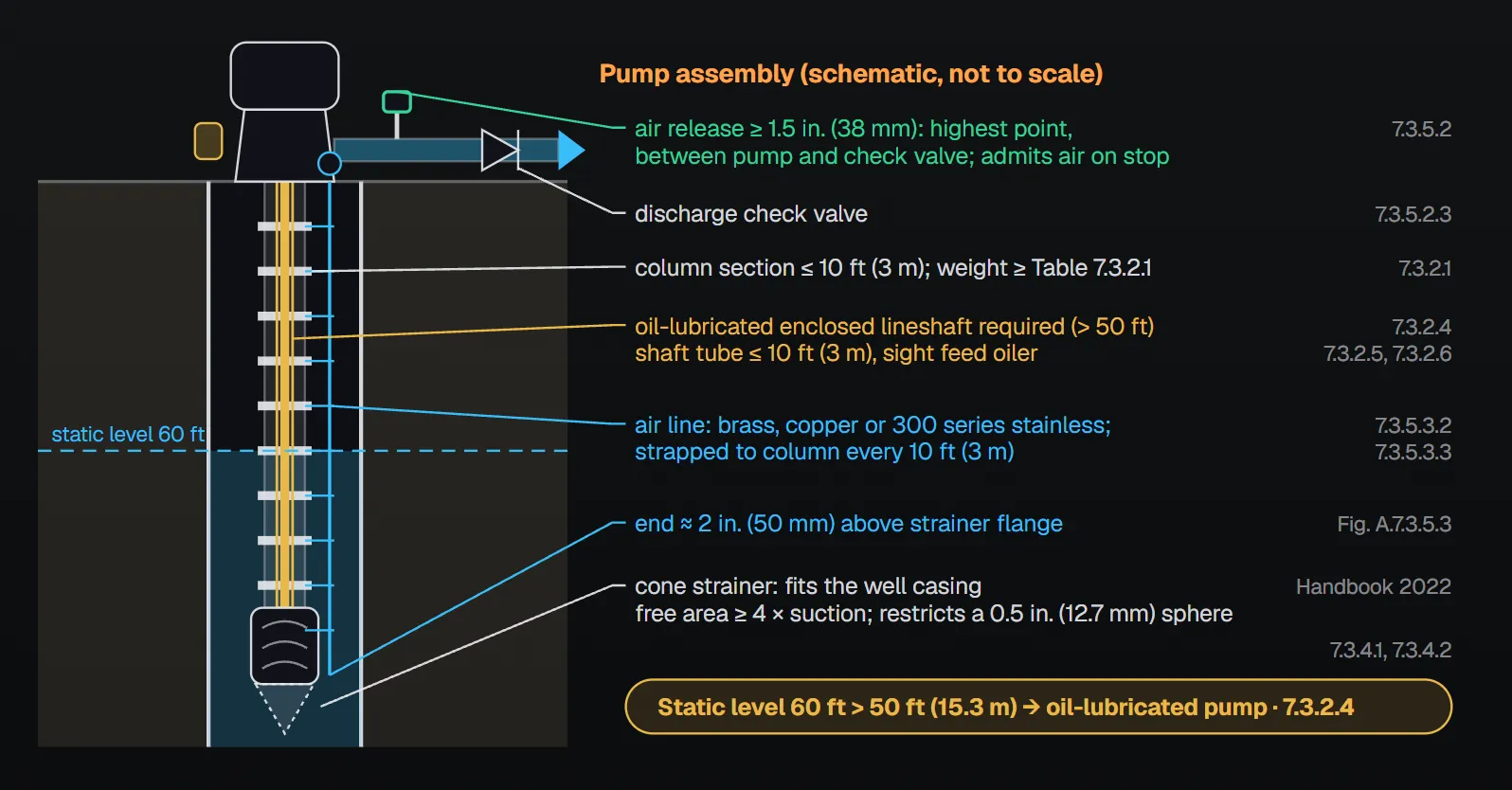
In short: the column is furnished in sections not exceeding a nominal 10 ft (3 m) and not lighter than Table 7.3.2.1(a)/(b) (7.3.2.1). Where the static water level is more than 50 ft (15.3 m) below ground, oil-lubricated pumps are used (7.3.2.4). Lineshafting is sized so the critical speed is 25 percent above and below the operating speed (7.3.2.7). The suction strainer free area is at least four times the suction connection area, and openings restrict a 0.5 in. (12.7 mm) sphere (7.3.4.2). A nominal 1.5 in. (38 mm) or larger automatic air release valve sits at the highest point between the pump and the discharge check valve (7.3.5.2.1, 7.3.5.2.3). Every turbine pump in a well has water level detection; air lines are strapped to the column at 10 ft (3 m) intervals (7.3.5.3, 7.3.5.3.3).
Pump head (7.3.1)
- The head is either the aboveground or belowground discharge type (7.3.1.1, Figure A.7.3.1 belowground discharge arrangement).
- The head is designed to support the driver, pump, column assembly, bowl assembly, maximum down thrust and the oil tube tension nut or packing container (7.3.1.2).
- The sealing type is packing (7.3.1.3).
Column (7.3.2)
The column is furnished in sections not exceeding a nominal 10 ft (3 m), not less than the weights in the tables below, connected by threaded-sleeve couplings or flanges (7.3.2.1). Threaded section ends are faced parallel and machined to butt, and flange faces are parallel and machined for a rabbet fit, so the column aligns accurately (7.3.2.2, 7.3.2.3). Per Annex A.7.3.2.1, metric countries do not appear to have standardized flow ratings, so a soft metric conversion is used.
| Nominal size (in.) | Outside diameter (in.) | Weight per unit length, plain ends (lb/ft) |
|---|---|---|
| 6 | 6.625 | 18.97 |
| 7 | 7.625 | 22.26 |
| 8 | 8.625 | 24.70 |
| 9 | 9.625 | 28.33 |
| 10 | 10.75 | 31.20 |
| 12 | 12.75 | 43.77 |
| 14 | 14.00 | 53.57 |
Table 7.3.2.1(a), US customary.
| Nominal size (mm) | Outside diameter (mm) | Weight per unit length, plain ends (kg/m) |
|---|---|---|
| 150 | 161 | 28.230 |
| 200 | 212 | 36.758 |
| 250 | 264 | 46.431 |
| 300 | 315 | 65.137 |
| 350 | 360 | 81.209 |
Table 7.3.2.1(b), metric.
Lubrication and critical speed
- Where the static water level exceeds 50 ft (15.3 m) below ground, oil-lubricated pumps are used (7.3.2.4, Figure A.7.1.1).
- On enclosed-lineshaft oil-lubricated pumps the shaft-enclosing tube is furnished in interchangeable extra-strong pipe sections not over 10 ft (3 m) (7.3.2.5), with an automatic sight feed oiler on a mounting bracket connected to the shaft tube (7.3.2.6).
- Lineshafting is sized so the critical speed is 25 percent above and below the operating speed (7.3.2.7). Operating speed includes all speeds from shutoff to the 150 percent point, which vary on engine drives (7.3.2.8); for variable speed pressure limiting drives, all speeds from rated to minimum operating speed (7.3.2.9).
NFPA 20 Handbook (2022) reasoning: with static levels deeper than 50 ft, the stuffing box bearing of a water-lubricated open lineshaft could run dry at startup and be damaged; an oil-lubricated enclosed lineshaft protects the upper bearings, and grease or fresh water flush is not allowed. On start-up a pump generally passes a critical speed in 1 second or less without harm, but running at a critical speed is not recommended; experience shows a 25 percent margin is safe.
Bowl assembly (7.3.3)
The pump bowl is close-grained cast iron, bronze or another material suited to the chemical analysis of the water and experience in the area (7.3.3.1). Impellers are the enclosed type, of bronze or another suitable material on the same basis (7.3.3.2). Handbook (2022): shaft stretch lowers the efficiency of a semi-open impeller; enclosed impellers also generate less downthrust.
Suction strainer (7.3.4)
- A cast or heavy fabricated, corrosion-resistant metal cone or basket-type strainer is attached to the suction manifold (7.3.4.1).
- Free area is at least four times the area of the suction connections; openings restrict the passage of a 0.5 in. (12.7 mm) sphere (7.3.4.2).
- In a wet pit this strainer is required in addition to the intake screen (7.3.4.3, Figure A.7.2.2.2); for the screen see the suction screen and anti-vortex plate article.
Handbook (2022): cone strainers fit down the well casing, basket strainers use the most water in a wet pit; the strainer is required in addition to the intake screen because the screen alone could pass objects larger than 0.5 in. (12.7 mm).
Fittings attached to the pump (7.3.5)
- Automatic air release valve (7.3.5.2)
- Water level detector (7.3.5.3)
- Discharge pressure gauge (4.12.1)
- Relief valve and discharge cone where required by 4.20.1
- Hose valve header and hose valves (4.22.3) or metering devices (4.22.2)
The air release valve is nominal 1.5 in. (38 mm) pipe size or larger and vents air from the column and discharge head when the pump starts (7.3.5.2.1); it also admits air to dissipate the vacuum when the pump stops (7.3.5.2.2). It is located at the highest point in the discharge line between the fire pump and the discharge check valve (7.3.5.2.3). Handbook (2022): trapped air can damage the pump and system components and impair the fire protection system. Gauge rules are in the pressure gauges article.
Water level detection
Water level detection is required for all vertical turbine pumps installed in wells, to monitor the suction pressure available at shutoff, 100 percent and 150 percent flow and determine whether the pump runs within its design conditions (7.3.5.3). Each well has a suitable water level detector (7.3.5.3.1); an air line, if used, is brass, copper or series 300 stainless steel (7.3.5.3.2) strapped to the column at 10 ft (3 m) intervals (7.3.5.3.3). Annex A.7.3.5.3 describes the air line method: a line of known length extends below the lowest anticipated level; when air is pumped in, the gauge settles at the pressure that supports the water column forced out of the line. Converting that pressure with psi × 2.31 = ft (bar × 10.3 = m) and subtracting it from the line length gives the level. In the annex example, with L = 50 ft (15.2 m), the gauge reads 10 psi (0.68 bar) before the pump starts and 8 psi (0.55 bar) while running; the drawdown is 4.6 ft (1.4 m). In Figure A.7.3.5.3 the line ends approximately 2 in. (50 mm) above the strainer flange.
Installation (7.4)
Per Annex A.7.4, most of the unit is underground, so the work is checked as it progresses; the most common method uses a tripod or portable derrick over the well, checked for alignment, with stages added per the manufacturer’s instructions.
- Pump house: designed to offer the least obstruction to handling and hoisting vertical pump parts (7.4.1.1); Sections 4.14 and 11.3 also apply (7.4.1.2). Handbook (2022): the pump house normally has a roof hatch of at least 4 ft × 4 ft (1219 mm × 1219 mm) so the lineshaft can be removed for maintenance.
- Outdoors: if in special cases the authority having jurisdiction does not require a pump room, the driver is screened or enclosed and protected against tampering (7.4.2.1); the screen or enclosure is easily removable with ample ventilation (7.4.2.2).
- Foundation: certified dimension prints are obtained from the manufacturer (7.4.3.1); the foundation carries the entire weight of pump and driver plus the water in it (7.4.3.2); foundation bolts anchor the pump (7.4.3.3); the load on concrete does not exceed design standards (7.4.3.4).
- Level and plumb: on a short-coupled pump the top of the foundation is carefully leveled so the pump hangs freely over a well pit (7.4.3.5); on a well pump the head is positioned plumb over the well, which is not necessarily level (7.4.3.6).
- Sump or pit: I-beams are permitted (7.4.3.7.1); with a right-angle gear the driver is installed parallel to the beams (7.4.3.7.2).
Common field mistakes
- Air release valve downstream of the check valve: 7.3.5.2.3 requires the highest point between pump and check valve.
- No water level detection in a well: required by 7.3.5.3; per Annex A.7.2.2.1.3 a performance test is not possible without it.
- Water-lubricated shaft with a deep static level: beyond 50 ft (15.3 m) 7.3.2.4 requires oil lubrication.
- Only an intake screen in a wet pit: 7.3.4.3 also requires the pump strainer.
- Leveling the head of a well pump: 7.4.3.6 uses plumb over the well.
Checklist
- Column sections no more than 10 ft (3 m), weight not below Table 7.3.2.1, ends machined parallel (7.3.2.1–7.3.2.3)?
- Static level deeper than 50 ft (15.3 m): oil-lubricated shaft, tube and oiler (7.3.2.4–7.3.2.6)?
- Critical speed 25 percent away from the operating range (7.3.2.7–7.3.2.9)?
- Strainer: free area ≥ 4 × suction, no 0.5 in. (12.7 mm) sphere; in a wet pit, in addition to the screen (7.3.4)?
- Air release ≥ 1.5 in. (38 mm) at the highest point between pump and check valve (7.3.5.2)?
- Water level detector in wells; air line material and 10 ft (3 m) straps (7.3.5.3)?
- Foundation loads, bolts, level or plumb (7.4.3)?
Frequently Asked Questions
When is oil lubrication required on a vertical turbine pump?
Per NFPA 20-2025 7.3.2.4, oil-lubricated pumps are used where the static water level exceeds 50 ft (15.3 m) below ground. Handbook (2022) reasoning: on a water-lubricated open lineshaft, the stuffing box bearing could run dry at startup and be damaged.
How heavy must the column pipe be?
The column is furnished in sections not exceeding a nominal 10 ft (3 m) and not lighter than Tables 7.3.2.1(a) and (b) (7.3.2.1); for example 24.70 lb/ft for an 8 in. column and 36.758 kg/m for 200 mm.
Where does the air release valve go?
At the highest point in the discharge line between the fire pump and the discharge check valve (7.3.5.2.3). It is nominal 1.5 in. (38 mm) or larger, vents air on start and admits air to dissipate the vacuum on stop (7.3.5.2.1, 7.3.5.2.2).
How is the water level in the well measured?
Every well installation has a suitable water level detector (7.3.5.3.1). An air line, if used, is brass, copper or series 300 stainless steel strapped to the column at 10 ft (3 m) intervals (7.3.5.3.2, 7.3.5.3.3). Annex A.7.3.5.3 explains subtracting the air pressure head read on the gauge from the line length.
What are the turbine pump strainer requirements?
A cast or heavy fabricated, corrosion-resistant cone or basket strainer (7.3.4.1) with free area at least four times the suction connections and openings that restrict a 0.5 in. (12.7 mm) sphere (7.3.4.2). In a wet pit it is required in addition to the intake screen (7.3.4.3).

SprinkCalc — Fire Sprinkler Design Across Three Standards
SprinkCalc covers hazard classification, design density and area, K-factor selection, water demand and hydraulic calculations for NFPA 13, FM Global and BS EN 12845 in a single iOS app, and exports a professional PDF report.
Download SprinkCalc on the App Store
MEP Calc — 110+ Engineering Calculators
MEP Calc bundles 110+ engineering modules in one iOS app: 21 fire calculations plus heating, cooling, HVAC, plumbing, steam and natural gas.
Download MEP Calc on the App StoreNFPA 20-2025, Standard for the Installation of Stationary Pumps for Fire Protection: 4.12.1; 4.20.1; 4.22.2; 4.22.3; 7.3.1.1–7.4.3.7.2; Tables 7.3.2.1(a) and (b); Annex A.7.2.2.1.3, A.7.3.1, A.7.3.2.1, A.7.3.5.3, A.7.4, Figures A.7.1.1, A.7.3.1, A.7.3.5.3 (explanatory). NFPA 20 Handbook 2022 commentary: Sections 7.3 and 7.4.