The reliability of a well-supplied vertical turbine pump starts with the well itself. NFPA 20-2025 Sections 7.2.3–7.2.7 set who is responsible for the well, the casing, screen, cement and gravel rules in unconsolidated formations such as sands and gravels, consolidated (rock) formations, developing the well and the production test. Submergence and acceptance of the supply are in the water supply and submergence article.
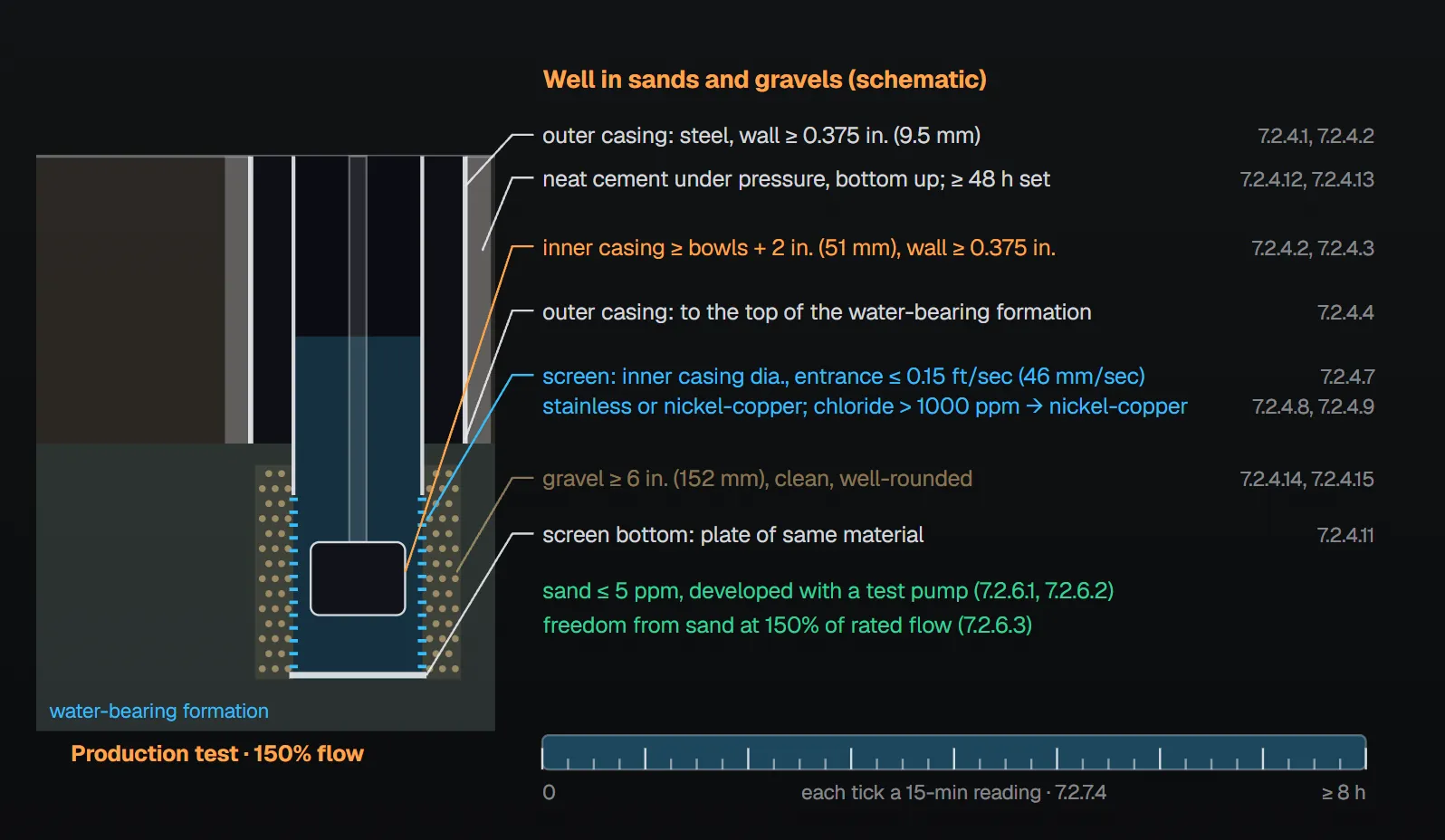
In short: investigation, well development and workmanship are the groundwater supply contractor’s responsibility (7.2.3.1). Casings are steel with a minimum wall thickness of 0.375 in. (9.5 mm) (7.2.4.1, 7.2.4.2); the inner casing is at least 2 in. (51 mm) larger than the pump bowls (7.2.4.3). Screen entrance velocity does not exceed 0.15 ft/sec (46 mm/sec) (7.2.4.7); nickel-copper alloy is used where chloride content will exceed 1000 ppm (7.2.4.9). The well is cleaned to not more than 5 ppm of sand with a test pump (7.2.6.1, 7.2.6.2). The production test runs at 150 percent of rated capacity for at least 8 continuous hours with 15-minute readings, and wells within 1000 ft (305 m) are monitored (7.2.7.4, 7.2.7.7).
Responsibility and straightness
The groundwater supply contractor is responsible for the groundwater investigation that establishes the reliability of the supply, for developing a well that produces the required supply and for performing all work and installing all equipment in a thorough and workmanlike manner (7.2.3.1). The well is of ample diameter and sufficiently plumb to receive the pump (7.2.3.2).
NFPA 20 Handbook (2022) commentary: the investigation is done before well construction and pump purchase; a critical item is the well water level with the pump at churn. If a large drawdown occurs at zero and 150 percent flow, fire protection components might not be installed to withstand the developed pressures. A casing that is not straight pushes against the pump and bends the column and shaft; the shaft then contacts the sleeve bearings, causing vibration and premature wear. The longer the column, the more critical straightness becomes. The Handbook (A.7.2.5 commentary) recommends straightness within 1 in./100 ft (25.4 mm/30.5 m) without a double bend, and “gauging” the well before installation by lowering a dummy assembly slightly longer and larger than the pump on a cable.
Unconsolidated formations: sands and gravels (7.2.4)
| Part | Rule | Clause |
|---|---|---|
| Casings | Steel; diameter and depth to suit the formation and conditions | 7.2.4.1 |
| Wall thickness | Inner and outer casings at least 0.375 in. (9.5 mm) | 7.2.4.2 |
| Inner casing diameter | At least 2 in. (51 mm) larger than the pump bowls | 7.2.4.3 |
| Outer casing | Down to approximately the top of the water-bearing formation | 7.2.4.4 |
| Inner casing and screen | As far into the formation as the water-bearing stratum justifies | 7.2.4.5 |
| Screen selection | A vital part of the construction; selected with care | 7.2.4.6 |
| Screen size and open area | Same diameter as the inner casing; length and open area for an entrance velocity not exceeding 0.15 ft/sec (46 mm/sec) | 7.2.4.7 |
| Screen material | Corrosion- and acid-resistant (such as stainless steel or nickel-copper alloy); nickel-copper alloy where chloride will exceed 1000 ppm | 7.2.4.8, 7.2.4.9 |
| Screen strength | Resists external forces after installation and minimizes damage during installation | 7.2.4.10 |
| Screen bottom | Sealed with a plate of the same material as the screen | 7.2.4.11 |
| Cement | Outer casing sides sealed with neat cement placed under pressure from bottom to top; at least 48 hours to set before drilling continues | 7.2.4.12, 7.2.4.13 |
| Gravel | At least 6 in. (152 mm) of clean, well-rounded gravel around the screen, forming a filter for sand-free production and low velocity | 7.2.4.14, 7.2.4.15 |
Handbook (2022) reasoning: the outer casing keeps the well walls from collapsing onto the lineshaft and pump and protects the bowls and column. Screen material and size are as essential as low entrance velocity; if the screen fails or is the wrong size, sand or rock can enter the well and damage impellers, bearings and other parts. Cement prevents the ingress of sand or rock; the work is usually a one-time event and is done with extreme care by experienced personnel.
Tubular wells
Wells developed in unconsolidated formations without an artificial gravel pack, such as tubular wells, are acceptable for fire pumps not exceeding 450 gpm (1703 L/min) (7.2.4.16.1). They comply with all of 7.2.3 and 7.2.4 except 7.2.4.11 through 7.2.4.15 (screen bottom plate, cement, setting time, gravel) (7.2.4.16.2).
Consolidated formations (7.2.5)
Where drilling penetrates unconsolidated formations above the rock, surface casing is installed, seated in solid rock and cemented in place (7.2.5). Per Annex A.7.2.5, where wells take their supply from rock, the well specifications are decided by the authority having jurisdiction after consulting a recognized groundwater consultant in the area. Handbook (2022): the surface casing keeps sand and rock from the overlying unconsolidated zone out of the well and prevents collapse of the walls.
Developing a well (7.2.6)
- Developing a new well and cleaning it of sand or rock particles, not to exceed 5 ppm, is the groundwater supply contractor’s responsibility (7.2.6.1).
- Development is performed with a test pump, not a fire pump (7.2.6.2).
- Freedom from sand is determined with the test pump at 150 percent of the rated capacity of the fire pump for which the well is prepared (7.2.6.3).
Handbook (2022): wells that are poorly constructed or produce sand can harm the pump; where excessive sand is suspected, a unit other than the fire pump must be used to clear the well.
Test and inspection of the well (7.2.7)
- A test is made to determine the water production of the well (7.2.7.1).
- An acceptable measuring device is used, such as an orifice, a venturi meter or a calibrated pitot tube (7.2.7.2).
- The test is witnessed by representatives of the customer, contractor and authority having jurisdiction, as required (7.2.7.3).
- The test is continuous for at least 8 hours at 150 percent of the fire pump rated capacity, with readings at 15-minute intervals (7.2.7.4).
- Evaluation considers the effect of other wells in the vicinity and possible seasonal variation of the water table at the site (7.2.7.5).
- Test data describe the static water level and the pumping water levels at 100 percent and 150 percent of rated capacity (7.2.7.6).
- All existing wells within a 1000 ft (305 m) radius of the fire well are monitored throughout the test (7.2.7.7).
Per Annex A.7.2.7, before the permanent pump is ordered the well water is analyzed for corrosiveness: pH, salts such as chlorides and harmful gases such as carbon dioxide (CO₂) or hydrogen sulfide (H₂S). If the water is corrosive, the pump is built of a suitable corrosion-resistant material or covered with special protective coatings per the manufacturer’s recommendations. Annex A.7.2.2.1.3 states that the acceptability of a well is determined by a 24-hour test flowing the well at 150 percent of the pump rating, reviewed by qualified personnel (usually a well drilling contractor or a person experienced in hydrology and geology).
Common field mistakes
- Developing the well with the fire pump: 7.2.6.2 requires a test pump.
- Inner casing with no clearance around the bowls: 7.2.4.3 requires at least 2 in. (51 mm) larger.
- Unsuitable screen material in chloride water: above 1000 ppm, 7.2.4.9 requires nickel-copper alloy.
- Drilling before the cement sets: 7.2.4.13 requires at least 48 hours.
- Short or low-flow production test: 7.2.7.4 requires at least 8 hours at 150 percent with 15-minute readings; nearby wells are monitored (7.2.7.7).
Checklist
- Groundwater investigation done before drilling and pump purchase (7.2.3.1)?
- Steel casings, at least 0.375 in. (9.5 mm); inner casing at least 2 in. (51 mm) larger than the bowls (7.2.4.1–7.2.4.3)?
- Screen: inner casing diameter, entrance velocity ≤ 0.15 ft/sec (46 mm/sec), suitable material, bottom plate (7.2.4.7–7.2.4.11)?
- Cement under pressure bottom to top, 48 hours set; at least 6 in. (152 mm) of gravel (7.2.4.12–7.2.4.14)?
- Sand not more than 5 ppm, verified with a test pump at 150 percent (7.2.6.1–7.2.6.3)?
- Production test: accepted device, at least 8 hours at 150 percent, 15-minute readings, static and 100/150 percent levels, nearby wells (7.2.7.2–7.2.7.7)?
Frequently Asked Questions
Who drills and develops a fire pump well?
Per NFPA 20-2025 7.2.3.1, the groundwater investigation, well development and all work are the groundwater supply contractor’s responsibility. Cleaning the well to not more than 5 ppm of sand is also theirs, done with a test pump, not the fire pump (7.2.6.1, 7.2.6.2).
What screen entrance velocity is allowed?
The screen has the same diameter as the inner casing, with length and open area for an entrance velocity not exceeding 0.15 ft/sec (46 mm/sec) (7.2.4.7). It is corrosion- and acid-resistant; nickel-copper alloy is used where chloride will exceed 1000 ppm (7.2.4.8, 7.2.4.9).
How long is the well production test?
At least 8 continuous hours at 150 percent of the fire pump rated capacity, with 15-minute readings (7.2.7.4). Annex A.7.2.2.1.3 mentions a 24-hour test at 150 percent for well acceptability; the mandatory minimum is the 8 hours of 7.2.7.4.
Can a tubular well supply a fire pump?
Yes, for fire pumps not exceeding 450 gpm (1703 L/min) (7.2.4.16.1). It complies with 7.2.3 and 7.2.4, except the screen bottom plate, cement, setting time and gravel rules of 7.2.4.11–7.2.4.15 (7.2.4.16.2).
Why are nearby wells monitored during the test?
The test is evaluated considering the effect of other wells in the vicinity and seasonal variation of the water table (7.2.7.5), and all existing wells within a 1000 ft (305 m) radius are monitored throughout the test (7.2.7.7).

SprinkCalc — Fire Sprinkler Design Across Three Standards
SprinkCalc covers hazard classification, design density and area, K-factor selection, water demand and hydraulic calculations for NFPA 13, FM Global and BS EN 12845 in a single iOS app, and exports a professional PDF report.
Download SprinkCalc on the App Store
MEP Calc — 110+ Engineering Calculators
MEP Calc bundles 110+ engineering modules in one iOS app: 21 fire calculations plus heating, cooling, HVAC, plumbing, steam and natural gas.
Download MEP Calc on the App StoreNFPA 20-2025, Standard for the Installation of Stationary Pumps for Fire Protection: 7.2.3.1–7.2.7.7; Annex A.7.2.2.1.3, A.7.2.5, A.7.2.7 (explanatory). NFPA 20 Handbook 2022 commentary: Sections 7.2.3–7.2.6.