Where the water supply is below the discharge flange centerline and the supply pressure is insufficient to deliver the water to the fire pump, NFPA 20-2025 requires a vertical shaft turbine-type pump (7.1.1). The centrifugal pumps of Chapter 6 are not used where a static suction lift is required (6.1.1.4). This article covers the opening of Chapter 7: application, performance limits, the water supply and how deep the pump is submerged. Developing and testing the well is covered in the well construction and test article; column, strainer and installation in the components and installation article.
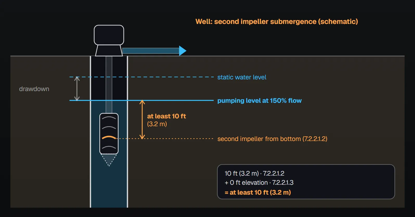
In short: in a well, the second impeller from the bottom stays at least 10 ft (3.2 m) below the pumping water level at 150 percent of rated capacity (7.2.2.1.2); submergence increases by 1 ft (0.3 m) for each 1000 ft (305 m) of elevation above sea level (7.2.2.1.3). In a wet pit, the second impeller is below the lowest pumping water level of the open body of water supplying the pit (7.2.2.2.1); at 2000 gpm (7570 L/min) or greater, additional submergence is required and obtained from the manufacturer (7.2.2.2.2, 7.2.2.2.3). The strainer bottom is at least one-half the bowl diameter, and not less than 12 in. (305 mm), above the pit bottom (7.2.2.2.4). The pump delivers 150 percent of rated capacity at not less than 65 percent of rated head and shutoff head does not exceed 140 percent (7.1.2.1, 7.1.2.2).
When is a vertical turbine pump required?
The rule is one sentence: where the water supply is below the discharge flange centerline and the supply pressure is insufficient to deliver the water to the fire pump, a vertical shaft turbine-type pump is used (7.1.1). Per Annex A.7.1.1, this pump is particularly suitable where the water source is below ground and it would be difficult to install any other type of pump below the minimum water level. It was originally designed for drilled wells but is permitted to lift water from lakes, streams, open swamps and other subsurface sources. Both oil-lubricated enclosed-lineshaft and water-lubricated open-lineshaft pumps are used (Figure A.7.1.1); some health departments object to oil-lubricated pumps and should be consulted before proceeding with that design.
Performance limits and vertical operation
- The pump furnishes not less than 150 percent of rated capacity at not less than 65 percent of total rated head (7.1.2.1).
- Total shutoff (churn) head does not exceed 140 percent of total rated head (7.1.2.2).
- The pump is designed to operate in a vertical position with all parts in correct alignment (7.1.2.3).
The curve end points are explained in the pump curve article. Annex A.7.1 notes that satisfactory operation depends largely on careful and correct installation and recommends that the work be done under the direction of a pump manufacturer’s representative. Handbook (2022) reasoning: installed level and plumb, the pump forms a protective water film between the shaft and the sleeve bearings; if the shaft is out of plumb it can contact the bearings, leading to vibration, premature wear and ultimately failure.
Water supply
The water supply is adequate, dependable and acceptable to the authority having jurisdiction (7.2.1.1). Per Annex A.7.2.1.1, stored water from reservoirs or tanks supplying wet pits is preferable; lakes, streams and groundwater are acceptable where investigation shows a suitable and reliable supply. The Handbook (2022) commentary points out that natural sources change level, can run dry in a drought and can carry abrasives such as sand, silt and gravel and chemicals that cause corrosion; seasonal fluctuation, snow and ice and trash accumulation are also considered.
Acceptance of a well depends on satisfactory development of the well and established satisfactory aquifer characteristics (7.2.1.2). Per Annex A.7.2.1.2, the authority having jurisdiction can require an aquifer performance analysis; the history of the water table is investigated, and the number of wells in use and likely to be in use is weighed against the total water available for fire protection. The Handbook (2022) recommends data not older than 10 years when establishing the minimum expected water level.
Submergence: wells (7.2.2.1)
- The pump bowls are submerged for reliable operation of the fire pump unit (7.2.2.1.1).
- The second impeller from the bottom of the bowl assembly is not less than 10 ft (3.2 m) below the pumping water level at 150 percent of rated capacity (7.2.2.1.2, Figure A.7.2.2.1).
- Submergence increases by 1 ft (0.3 m) for each 1000 ft (305 m) of elevation above sea level (7.2.2.1.3).
Annex A.7.2.2.1.3 gives the reasoning: 10 ft (3.05 m) is the minimum acceptable submergence for proper operation in wells, and the elevation increase is due to the loss of atmospheric pressure with elevation. Net positive suction head (NPSH) available must therefore be considered in pump selection: at 1000 ft (305 m) elevation, approximately 11 ft (3.35 m) of water is required to obtain the equivalent of 10 ft (3.05 m) of NPSH. The Handbook (2022) states that this increase is in addition to any other increases in the standard and that omitting it can lead to cavitation at higher flows. Manufacturers’ and the Hydraulic Institute’s minimum submergence values prevent surface vortices only, not cavitation; the designer also checks the required NPSH at runout (Handbook 2022, 7.2.2 commentary).
The difference between the static level and the pumping level is the drawdown. In Figure A.7.2.2.1 the minimum submergence is measured from the pumping water level at 150 percent, not from the static level.
Submergence: wet pits (7.2.2.2)
- To provide submergence for priming, the second impeller from the bottom is below the lowest pumping water level in the open body of water supplying the pit (7.2.2.2.1).
- For pumps rated 2000 gpm (7570 L/min) or greater, additional submergence is required to prevent vortices and to provide the NPSH that prevents excessive cavitation (7.2.2.2.2); the required submergence is obtained from the pump manufacturer (7.2.2.2.3).
- The distance from the bottom of the strainer to the bottom of the wet pit is at least one-half the pump bowl diameter and not less than 12 in. (305 mm) (7.2.2.2.4).
- In a wet pit the pump suction strainer is required in addition to the intake screen (7.3.4.3); screen rules are in the suction screen and anti-vortex plate article.
Annex A.7.2.2.2 recommends that velocities in the approach channel or intake pipe not exceed approximately 2 ft/sec (0.7 m/sec) and in the wet pit approximately 1 ft/sec (0.3 m/sec). The ideal approach is a straight channel coming directly to the pump; turns and obstructions can cause eddy currents and initiate deep-cored vortices. The submergence needed depends greatly on the intake approach and the pump size. The annex points to ANSI/HI 9.8 for sump dimensions at flows of 3000 gpm (11,355 L/min) and larger, and to the same general principles for smaller pumps. Handbook (2022) commentary: uneven flow forms surface or submerged vortices; with low submergence air enters the pump, capacity drops and vibration and noise increase. Water should not flow past one pump intake to reach the next.
| Item | Well | Wet pit |
|---|---|---|
| Reference level | Pumping water level at 150 percent flow (7.2.2.1.2) | Lowest pumping water level of the supplying open water (7.2.2.2.1) |
| Second impeller from bottom | At least 10 ft (3.2 m) below | Below that level; additional submergence at 2000 gpm (7570 L/min) or greater, value from the manufacturer (7.2.2.2.2, 7.2.2.2.3) |
| Elevation increase | 1 ft (0.3 m) per 1000 ft (305 m) (7.2.2.1.3) | 7.2.2.1.3 sits under the well heading |
| Clearance below strainer | — | One-half bowl diameter, not less than 12 in. (305 mm) (7.2.2.2.4) |
| Approach velocity (Annex A) | — | Channel or pipe ≈ 2 ft/sec (0.7 m/sec), pit ≈ 1 ft/sec (0.3 m/sec) (A.7.2.2.2) |
Common field mistakes
- Measuring submergence from the static level: 7.2.2.1.2 uses the pumping water level at 150 percent flow.
- Skipping the elevation increase: the Handbook (2022) warns of cavitation at higher flows (7.2.2.1.3).
- Relying on vortex submergence alone: the Handbook (2022) notes it does not prevent cavitation; required NPSH at runout is checked separately.
- Strainer too close to the floor: 7.2.2.2.4 requires one-half bowl diameter and not less than 12 in. (305 mm).
- Pump not primed: Annex B.1.19 says to check the water level of a vertical shaft turbine pump to see whether the bowls have proper submergence.
Checklist
- Is the water below the discharge flange centerline with insufficient supply pressure (7.1.1)?
- Is the supply adequate, dependable and accepted; for a well, are aquifer characteristics established (7.2.1.1, 7.2.1.2)?
- In a well, is the pumping level at 150 percent flow known and the second impeller at least 10 ft (3.2 m) below it (7.2.2.1.2)?
- Is the elevation increase added (7.2.2.1.3)?
- In a wet pit: lowest level, additional submergence at 2000 gpm or greater, strainer clearance (7.2.2.2.1–7.2.2.2.4)?
Frequently Asked Questions
When is a vertical turbine pump required?
Per NFPA 20-2025 7.1.1, where the water supply is below the discharge flange centerline and the supply pressure is insufficient to deliver the water to the fire pump. Chapter 6 centrifugal pumps are not used where a static suction lift is required (6.1.1.4).
How deep is the pump submerged in a well?
The second impeller from the bottom of the bowl assembly is not less than 10 ft (3.2 m) below the pumping water level at 150 percent of rated capacity (7.2.2.1.2), plus 1 ft (0.3 m) for each 1000 ft (305 m) of elevation above sea level (7.2.2.1.3).
Why does elevation increase submergence?
Per Annex A.7.2.2.1.3, atmospheric pressure drops with elevation, so NPSH available must be considered. In the annex example, about 11 ft (3.35 m) of water is required at 1000 ft (305 m) to obtain the equivalent of 10 ft (3.05 m) of NPSH.
How is wet pit submergence determined?
The second impeller is below the lowest pumping water level of the open water supplying the pit (7.2.2.2.1). Pumps rated 2000 gpm (7570 L/min) or greater need additional submergence, obtained from the pump manufacturer (7.2.2.2.2, 7.2.2.2.3).
What clearance is needed below the strainer in a wet pit?
At least one-half the pump bowl diameter, but not less than 12 in. (305 mm) (7.2.2.2.4). Annex A.7.2.2.2 also recommends a wet pit velocity of no more than approximately 1 ft/sec (0.3 m/sec).

SprinkCalc — Fire Sprinkler Design Across Three Standards
SprinkCalc covers hazard classification, design density and area, K-factor selection, water demand and hydraulic calculations for NFPA 13, FM Global and BS EN 12845 in a single iOS app, and exports a professional PDF report.
Download SprinkCalc on the App Store
MEP Calc — 110+ Engineering Calculators
MEP Calc bundles 110+ engineering modules in one iOS app: 21 fire calculations plus heating, cooling, HVAC, plumbing, steam and natural gas.
Download MEP Calc on the App StoreNFPA 20-2025, Standard for the Installation of Stationary Pumps for Fire Protection: 6.1.1.4; 7.1.1–7.1.2.3; 7.2.1.1–7.2.2.2.4; 7.3.4.3; Annex A.7.1, A.7.1.1, A.7.2.1.1, A.7.2.1.2, A.7.2.2.1.3, A.7.2.2.2, Figures A.7.1.1, A.7.2.2.1, A.7.2.2.2 (explanatory); Annex B.1.19. NFPA 20 Handbook 2022 commentary: Sections 7.1, 7.2.1 and 7.2.2.