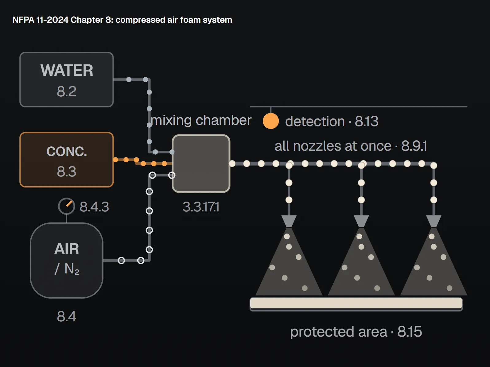
A compressed air foam system (CAFS) makes its foam at the head of the system rather than at the nozzle. Water, foam concentrate and air or nitrogen under pressure meet in a mixing chamber, and what travels down the pipe is finished foam, not solution. NFPA 11-2024 gives these systems Chapter 8. The chapter is short: most of the design is tied to the manufacturer’s listed design manual. This article follows Chapter 8 in order and collects the related rules in Chapters 5 and 12.
Clause numbers and values were read from the page images of NFPA 11-2024. Topics the standard hands to other standards are not described; Annex A text is explanatory and marked as such.
Definitions: CAF, CAFS and the generating method
- Compressed air foam (CAF): homogeneous, micro-size bubbles produced by combining water, concentrate and air or nitrogen under pressure (3.3.9.1).
- CAFS: a system in which foam is carried from a mixing chamber through fixed piping to compressed air foam nozzles, Type II and Type III applicators or devices, or hoses (3.3.16.1).
- Generating method: combining air or nitrogen under pressure, water and concentrate in the correct proportions in a mixing chamber (3.3.17.1).
- Discharge device: a device designed specifically to discharge compressed air foam in a predetermined pattern (3.3.2.2).
The Annex A note explains that discharge starts with automatic detection or manual actuation, after which foam from the mixing chamber flows through the piping to the devices or hoses. It adds that CAFS may protect ignitable liquids but is not used on oxygen-releasing chemicals such as cellulose nitrate, energised unenclosed electrical equipment, water-reactive metals and materials, or liquefied flammable gas (A.3.3.16.1, Annex A, explanatory).
The logic of Chapter 8: everything follows the listing
Chapter 8 governs the correct use of CAFS components (8.1.1). Every component must be listed for its intended use, and where no listing exists the component must be approved (8.1.2, 8.1.2.1). The foam-generating method is listed as well (8.5). The system is designed and installed to its listing for the hazards and protection objectives that listing names; the limits sit in the manufacturer’s listed design manual, which forms part of the listing (8.10.1, 8.10.2, 8.11). The manual comes first; NFPA 11 sets the frame and a few floors.
Water, concentrate and air: three supplies
The third fluid is what sets CAFS apart from foam-water systems. The standard treats water, concentrate and air or nitrogen in much the same way: quality, quantity, reserve, storage and supervision. The table lines the three supplies up.
| Topic | Water (8.2) | Concentrate (8.3) | Air or nitrogen (8.4) |
|---|---|---|---|
| Quality | Hard or soft, fresh or salt, provided foam formation and stability are not harmed; no additives without consulting the concentrate supplier (8.2.1). | Listed for use with the equipment; quality is confirmed by tests (8.3.1). | Storage containers are listed; pressure regulators are listed for the purpose (8.4.2.1, 8.4.4). |
| Quantity | All devices and CAF hoses that may run at once, for the specified time, plus other firefighting and normal plant demand (8.2.2). | Enough for the largest single hazard or a group protected simultaneously (8.3.2). | Same test: largest single hazard or simultaneous group (8.4.1.1). |
| Reserve | — | Enough to return the system to service: separate tanks or compartments, drums or cans on site, or an approved outside source within 24 hours (8.3.5). | Enough to return the system to service, or from an approved outside source within 24 hours (8.4.1.2). |
| Pressure, temperature | At the required flow, at least the design minimum at the system inlet (8.2.3); water between 4°C and 38°C (40°F and 100°F) (8.2.4). | Stored within its listed temperature limits (8.3.4). | Pressure supervised for both high and low pressure (8.4.3). |
| Storage | Protected against freezing where freezing is expected (8.2.6); the water system is designed and installed to NFPA 24 (8.2.5). | Tanks of corrosion-resistant material compatible with the concentrate, designed with evaporation in mind and marked with concentrate type and concentration (8.3.3). | Pressurised containers meet transport rules, are stamped to ASME Section VIII, are kept from severe weather and damage, and each has a releasing device (8.4.2.2–8.4.2.4). |
Concentrate types are never mixed in storage, and brands of one type only with manufacturer data and AHJ acceptance (8.3.6). Two routes are open for air. Plant air may be used where it meets the listing’s requirements for a dedicated main and reserve supply and the AHJ approves (8.4.5). A compressor dedicated to the system must be listed for fire protection service (8.4.6).
Distribution, nozzles and flow calculation
- Pipe and fittings: pipe follows 4.7.2.3, so pipe within the hazard area is rated for the pressure and temperature involved; fittings follow 4.7.3 (8.6.1, 8.6.2). Piping is installed to NFPA 13 (8.12).
- Nozzles: listed for the purpose and protected from mechanical, chemical, climatic or other damage (8.7.1, 8.7.2); layout keeps to the listing’s limits on spacing, floor coverage and alignment (8.14.1, 8.14.2).
- Flow calculation: CAF flow is both hydraulic and pneumatic, and the design treats the two together so the bubble structure survives until discharge (8.17.1). Calculations use a compressed air foam method within the manufacturer’s design manual (8.17.2); a listed pre-engineered design needs none (8.17.3). Pipe lengths and fitting and nozzle configurations stay within the listed limits (8.17.4).
NFPA 11 leaves the calculation method to the manufacturer’s manual, so the plan submittal asks separately for an air quantity calculation and a CAFS flow calculation report (9.3.3).
System types and actuation
A Chapter 8 system is a fixed deluge-type system, a fixed spray-type system, or a fixed or semi-fixed piped Type II or Type III application. In every case foam must discharge from all nozzles and devices at the same time once the system actuates (8.9.1). The system may protect a single zone or several zones (8.9.2).
Operation and control follow Section 4.9 (8.8.1): systems may actuate automatically or manually, every system keeps a means of manual actuation, and an automatic system is set off by automatic detection equipment (4.9.1.1, 4.9.1.2, 4.9.2.1). Installation of automatic detection devices is left to NFPA 72 (8.13).
Discharge density and duration (8.15, 8.16)
Design density follows the occupancy standards and the manufacturer’s listing, but never falls below these floors:
| Rule | Value | Clause |
|---|---|---|
| Minimum density, hydrocarbon fuel | 1.63 mm/min (0.04 gpm/ft²) | 8.15 |
| Minimum density, alcohol and ketone | 2.3 mm/min (0.06 gpm/ft²) | 8.15 |
| Fixed spray system on three-dimensional equipment | Minimum density applied over the projected area of the rectangular prism enclosing the equipment and its appurtenances | 8.15.1 |
| Minimum duration, deluge type | 10 min over the entire area | 8.16.1 |
| Minimum duration, fixed spray type | 5 min | 8.16.1 |
| Back-up sprinkler protection | Permitted where the AHJ requires it | 8.16.2 |
Duration must also agree with the manufacturer’s listing (8.16.1); where the listing calls for a higher density or a longer time, the listing governs. One mm/min is the same as one L/min·m² (footnote to Table 5.7.3.2). A simple arithmetic example: on a 100 m² hydrocarbon area the floor density gives 100 × 1.63 = 163 L/min, and a deluge-type system running for 10 minutes needs at least 1630 L. The product only shows the floor; nozzle count, spacing and actual flow come from the listed manual. For general foam design criteria, see the NFPA 11 Design Criteria Calculator.
CAFS in Chapter 5: tanks, loading racks and dikes
- Outdoor fixed-roof tanks: foam monitors and handlines, and fixed discharge outlets, both including those supplied by compressed air foam generation technology (5.2).
- Loading racks: foam nozzles using compressed air foam delivery systems, and foam monitors using compressed air foam delivery (5.6.3).
- Diked areas: Table 5.7.3.2 gives compressed air foam technology its own row. It sets no number for the application rate and points to the manufacturer’s listed minimum; the minimum discharge times match the other rows.
| Table 5.7.3.2: diked area, hydrocarbons | Minimum application rate | Class I time | Class II time |
|---|---|---|---|
| Low-level foam discharge outlets | 4.1 mm/min (0.10 gpm/ft²) | 30 min | 20 min |
| Foam monitors | 6.5 mm/min (0.16 gpm/ft²) | 30 min | 20 min |
| Foam using compressed air foam technology | Manufacturer’s listed minimum | 30 min | 20 min |
For the other dike, spill area and loading rack rules, see NFPA 11 Dikes, Spill Areas and Loading Racks.
Plans, acceptance testing and maintenance
Plans and specifications follow Chapter 9 (8.18). Its plan list has two CAFS-specific entries: a calculation of the required amount of air and a CAFS flow calculation report (9.3.3 (28), (29)). Testing follows Chapter 12 (8.19), which has three rules written for CAFS:
- Pipe interiors are carefully examined by eye during installation and cleaned where needed (12.2.5.1).
- After installation the piping is flushed with the system’s own air supply instead of water (12.2.5.2).
- Every discharge test records static water pressure, residual water pressure at the control valve, system air pressure and foam solution concentration (12.6.3.1).
Maintenance follows Chapter 13 (8.20). For the general acceptance tests see NFPA 11 Acceptance Tests, and for concentrate supply and reserve see NFPA 11 Foam Concentrate Supply and Proportioning.
Common mistakes
- Treating the 1.63 and 2.3 mm/min values in 8.15 as design values: they are floors, and the listing may ask for more.
- Planning the concentrate reserve and forgetting the air or nitrogen reserve, which carries the same 24-hour rule (8.4.1.2).
- Connecting plant air without AHJ approval (8.4.5), or using a compressor not listed for fire protection service (8.4.6).
- Flushing CAFS piping with water; it is flushed with the system’s air (12.2.5.2).
Frequently Asked Questions
What is the minimum CAFS discharge density?
1.63 mm/min (0.04 gpm/ft²) for hydrocarbon fuels and 2.3 mm/min (0.06 gpm/ft²) for alcohols and ketones (8.15). These are floors; where the occupancy standard or the manufacturer’s listing gives more, that applies.
How long must a CAFS discharge?
At least 10 minutes over the entire area for deluge-type systems and at least 5 minutes for fixed spray-type systems, and in line with the manufacturer’s listing (8.16.1).
Does a CAFS need a reserve of air or nitrogen?
Yes. A reserve sufficient to return the system to service is provided, or it is available from an approved outside source within 24 hours (8.4.1.2). Air or nitrogen pressure is supervised for high and low pressure (8.4.3).
How is CAFS piping flushed after installation?
With the system’s own air supply instead of water (12.2.5.2). Pipe interiors are carefully examined during installation and cleaned where needed (12.2.5.1).
What application rate applies to compressed air foam on a diked area?
Table 5.7.3.2 gives no number and points to the manufacturer’s listed minimum application rate. Minimum discharge time is 30 minutes for Class I and 20 minutes for Class II hydrocarbons.

SprinkCalc — Fire Sprinkler Design Across Three Standards
SprinkCalc covers hazard classification, design density and area, K-factor selection, water demand and hydraulic calculations for NFPA 13, FM Global and BS EN 12845 in a single iOS app, and exports a professional PDF report.
Download SprinkCalc on the App Store
MEP Calc — 110+ Engineering Calculators
MEP Calc bundles 110+ engineering modules in one iOS app: 21 fire calculations plus heating, cooling, HVAC, plumbing, steam and natural gas.
Download MEP Calc on the App StoreNFPA 11, Standard for Low-, Medium-, and High-Expansion Foam, 2024 edition: 3.3.2.2, 3.3.9.1 (p. 11-10); 3.3.16.1, 3.3.17.1 (pp. 11-11, 11-12); 4.7.2.3 (p. 11-16); 4.9.1, 4.9.2.1, 5.2 (p. 11-18); 5.6.3 (p. 11-27); Table 5.7.3.2 (p. 11-28); 8.1–8.2.3 (p. 11-42); 8.2.4–8.9.1 (p. 11-43); 8.9.2–8.20 (p. 11-44); 9.3.3 (pp. 11-44, 11-45); 12.2.5, 12.6.3.1 (p. 11-51); Annex A: A.3.3.16.1 (p. 11-59). The area in the worked example is an assumption. The binding text is the standard itself and the decision of the authority having jurisdiction.