The design criteria of a foam system are the written answer to “how much foam, for how long, and from where”. NFPA 11-2024 does not give that answer as one formula but as tables split by hazard. This article walks through the order in which a low-expansion foam criteria sheet is filled and the clauses behind each line. The NFPA 11 design criteria wizard follows the same order and gives every line with its clause number.
In short: choose the hazard and protection method (Chapter 5 or 6). Read the minimum application rate and time from the table. Multiply the rate by the protected area to get the solution flow. Add the outlets and supplementary hose streams. Work out the concentrate from the proportioning percentage and the solution volume, then add a reserve that covers the worst case (4.3.2.5).
Step 1: Define the hazard and protection method
Chapter 5 of NFPA 11 splits low-expansion foam by hazard. Each heading has its own table, its own times and its own limits:
- Fixed-roof (cone) tanks: fixed Type II outlets (5.2.5), subsurface injection (5.2.6) or monitors and handlines (5.2.4).
- Open-top floating roof tanks: seal area protection (5.3). Subsurface and semisubsurface injection are not used on these tanks (5.3.3.1), and monitors may not be the primary means of seal-fire extinguishment (5.3.7).
- Indoor tanks: indoor storage tanks with liquid surfaces of 37 m² (400 ft²) or more (5.5.1).
- Loading racks, diked areas and nondiked spills: 5.6, 5.7 and 5.8.
- Foam-water sprinkler and spray systems: Chapter 6. See design area, spacing and duration.
The choice of method closes some doors. Subsurface injection is not used for Class IA hydrocarbons or for alcohols, esters, ketones, aldehydes, anhydrides and other products requiring alcohol-resistant foam (5.2.6.1.1). Fixed outlets are not used on horizontal or pressure tanks (5.2.3). Handlines may not be the primary protection of fixed-roof tanks over 9 m (30 ft) in diameter or 6.1 m (20 ft) in height (5.2.4.1.2).
Step 2: Define the liquid and foam type
For hydrocarbons the tables split the liquid by flash point: 38–60 °C (100–140 °F), below 38 °C or heated above its flash point, and crude petroleum. The time depends on this split. Water-soluble and polar liquids that destroy regular foam require alcohol-resistant foam, and the concentrate must be listed for that liquid (4.3.1.2.1, 5.2.5.3.1). For these liquids NFPA 11 mostly gives no rate; it comes from the manufacturer’s listing or from fire tests (Table 5.2.5.3.4, 5.5.4, Table 5.6.5.3.1, 5.7.4.3.2, Table 5.8.1.2).
Step 3: Read the minimum rate and time
The table below brings together the most used values. Each row comes from NFPA 11-2024’s own table; see the clause for detail and special cases.
| Hazard and method | Minimum rate | Minimum time | Source |
|---|---|---|---|
| Fixed roof, Type II outlet, hydrocarbon | 4.1 mm/min (0.10 gpm/ft²) | 38–60 °C: 30 min · below 38 °C and crude: 55 min | Table 5.2.5.2.2 |
| Fixed roof, subsurface, hydrocarbon | 4.1 mm/min, max 8.1 mm/min | 30 / 55 / 55 min | Table 5.2.6.5.1 |
| Fixed roof, monitor or handline | 6.5 mm/min (0.16 gpm/ft²) × at least 1.5 | 50 / 65 / 65 min | Table 5.2.4.2.2, 5.2.4.2.1.2 |
| Floating roof, top of seal (with dam) | 12.2 mm/min (0.3 gpm/ft²) | 20 min | Table 5.3.5.3.1 |
| Floating roof, below the seal | 20.4 mm/min (0.5 gpm/ft²) | 10 min | Table 5.3.5.3.6.1 |
| Indoor tank, hydrocarbon | 6.5 mm/min | Table 5.2.5.2.2 time | 5.5.3.1, 5.5.3.2 |
| Dike, low-level outlets / monitors | 4.1 / 6.5 mm/min | Class I 30 min · Class II 20 min | Table 5.7.3.2 |
| Loading rack, monitors | Protein/FP/SFFF 6.5 · AFFF/FFFP 4.1 mm/min | 15 min | Table 5.6.5.3.1 |
| Nondiked spill, portable nozzles/monitors | Protein/FP/SFFF 6.5 · AFFF/FFFP 4.1 mm/min | 15 min | Table 5.8.1.2 |
| Foam-water sprinklers | at least 6.5 mm/min | 10 min | 6.5.2.2.1, 6.5.2.3.1 |
Table values are minimums. For fixed-roof tanks, subsurface injection, top-of-seal floating roof protection and indoor tanks, a higher applied rate allows the time to be reduced in proportion, but never below 70% of the table time (5.2.5.2.3, 5.2.6.5.3, 5.3.5.3.4, 5.5.3.3). For foam-water sprinklers the same idea is limited to 7 minutes (6.5.2.3.2). The rate–time relationship is covered in application rate and discharge time.
Step 4: Work out the solution flow
The mm/min in the tables equals L/min·m² (table notes), so the solution flow is the rate times the protected area: Q = r × A. The protected area depends on the hazard: the liquid surface of a fixed-roof tank, the annulus between shell and foam dam on a floating roof, the ground area within the curb at a rack (5.6.5.1), the dike area, or the estimated spill area (5.8.1.1). For monitors and handlines the rate is increased by a factor of at least 1.5 for wind and ambient losses (5.2.4.2.1.2).
Step 5: Add outlets and supplementary hose streams
On a fixed-roof tank the number of outlets comes from Table 5.2.5.2.1 by diameter: 1 up to 24 m, 2 up to 37 m, 3 up to 43 m, 4 up to 49 m, 5 up to 55 m, 6 up to 61 m, plus one for each additional 465 m² (5000 ft²) on larger tanks. Subsurface injection has its own table (Table 5.2.6.2.8), and floating roofs have outlet spacing tables (Tables 5.3.5.3.1 and 5.3.5.3.6.1). Outlets are spaced equally around the periphery and each is sized to deliver at least the minimum rate (5.2.5.1.2, 5.2.5.1.2.2).
In addition to the tank installation, approved foam hose stream equipment is provided for small spill fires (5.9.2.1). The number and time follow the largest tank diameter on site, and each stream delivers at least 190 L/min (50 gpm) of solution (5.9.2.3). See supplementary hoses and monitors.
| Largest tank diameter | Hose streams (Table 5.9.2.2) | Largest tank diameter | Time (Table 5.9.2.4) |
|---|---|---|---|
| Up to 20 m (65 ft) | 1 | Up to 11 m (35 ft) | 10 min |
| 20–36 m (65–120 ft) | 2 | 11–29 m (35–95 ft) | 20 min |
| Over 36 m (120 ft) | 3 | Over 29 m (95 ft) | 30 min |
Step 6: Choose the design hazard
Where there are several tanks, the system is designed for the tank needing the largest solution flow, including supplementary hose streams (5.2.2). The concentrate, however, must cover the largest single hazard or group of hazards protected simultaneously (4.3.2.2). The two do not always point to the same tank. Annex A.4.3.2.2 (explanatory) gives an example: a tank with a smaller flow but a longer time can need more concentrate. Each hazard is therefore calculated, and the largest flow and the largest quantity are taken separately.
Step 7: Work out concentrate and reserve
Concentrate consumption follows the proportioning percentage used in the design (4.3.2.5.1): main quantity = percentage × (Q × t + hose flow × hose time). In atmospheric concentrate tanks, concentrate below the suction inlet is not counted as usable (4.3.2.3.1.5), and the sediment pocket volume is added to the required quantity (4.3.2.3.2.3). The reserve meets the design requirements of the worst-case fire and puts the system back in service (4.3.2.5.2.1); it is kept on site in separate tanks, drums or cans, or obtainable from an approved outside source within 24 hours (4.3.2.5.2.2).
Example: a 30 m fixed-roof petrol tank
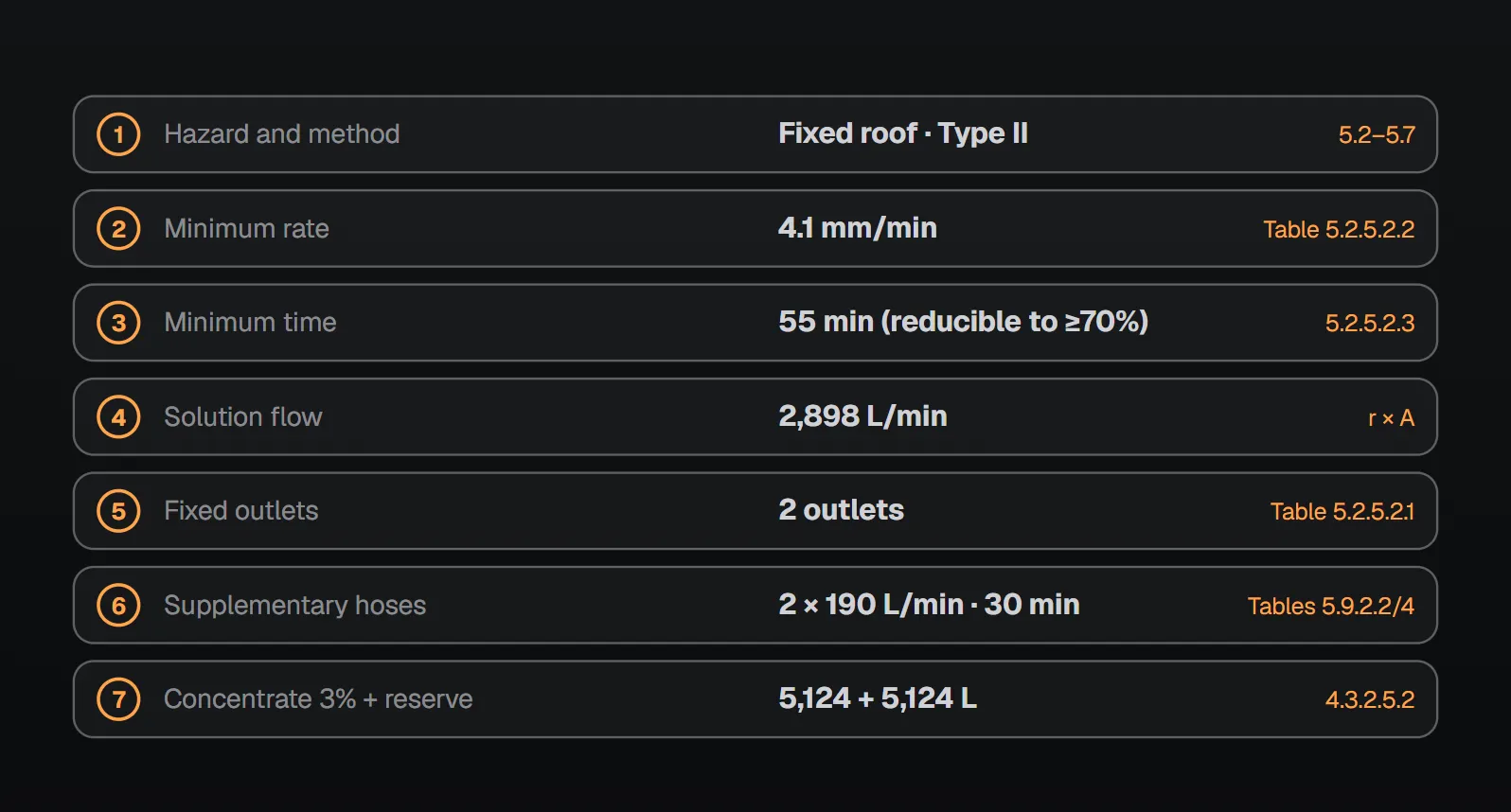
A hydrocarbon with a flash point below 38 °C, protected by fixed Type II outlets. Liquid surface π × 30² / 4 ≈ 706.9 m². Table 5.2.5.2.2 gives at least 4.1 mm/min for 55 min: Q = 4.1 × 706.9 ≈ 2,898 L/min. Table 5.2.5.2.1 gives 2 outlets. If this is the largest tank on site, Tables 5.9.2.2 and 5.9.2.4 give 2 hose streams of 190 L/min for 30 min. Solution volume 2,898 × 55 + 2 × 190 × 30 ≈ 170,800 L. With 3% concentrate the main quantity is about 5,124 L, and about 10,248 L with an equal reserve. The sediment pocket and the volume below the suction are added on top.
Where NFPA 11 gives no number
Some lines on the sheet are left blank on purpose. The rate for polar liquids, the minimum for compressed air foam (Table 5.7.3.2) and the application rate with SFFF (6.5.2.2.1.1) are left to the manufacturer and the listing. In all cases the concentrate and foam-equipment manufacturers are consulted on limitations based on listings or fire tests (5.2.4.3.3, 5.2.5.3.2). These values go on the sheet from the manufacturer’s document, not from a guess.
Frequently Asked Questions
In what order are NFPA 11 design criteria set?
Hazard and protection method, liquid and foam type, minimum rate and time from the table, solution flow (rate × area), number of outlets, supplementary hose streams, choice of the design hazard (5.2.2, 4.3.2.2), and finally concentrate and reserve (4.3.2.5).
What is the minimum foam rate for a fixed-roof hydrocarbon tank?
With fixed Type II outlets, 4.1 mm/min (0.10 gpm/ft²); the time is 30 min at a flash point of 38–60 °C (100–140 °F), and 55 min below that or for crude (Table 5.2.5.2.2).
Which tank governs the design?
For flow, the tank needing the largest solution flow including supplementary hose streams (5.2.2); for concentrate, the largest single hazard or group protected simultaneously (4.3.2.2). Per Annex A.4.3.2.2 the largest flow does not necessarily dictate the largest quantity.
How large is the concentrate reserve?
Enough to meet the design requirements of the worst-case fire and put the system back in service (4.3.2.5.2.1). It is kept on site in separate tanks or drums, or obtainable from an approved outside source within 24 hours (4.3.2.5.2.2).
Does NFPA 11 give a rate for polar liquids?
Mostly not. For liquids requiring alcohol-resistant foam the rate is left to the manufacturer’s listing or fire tests (e.g., Table 5.2.5.3.4, 5.7.4.3.2). On fixed-roof tanks with Type II outlets the time is 55 min.

SprinkCalc — Fire Sprinkler Design Across Three Standards
SprinkCalc covers hazard classification, design density and area, K-factor selection, water demand and hydraulic calculations for NFPA 13, FM Global and BS EN 12845 in a single iOS app, and exports a professional PDF report.
Download SprinkCalc on the App Store
MEP Calc — 110+ Engineering Calculators
MEP Calc bundles 110+ engineering modules in one iOS app: 21 fire calculations plus heating, cooling, HVAC, plumbing, steam and natural gas.
Download MEP Calc on the App StoreNFPA 11-2024, Standard for Low-, Medium-, and High-Expansion Foam: 4.3.1.2.1, 4.3.2.2, 4.3.2.3.1.5, 4.3.2.3.2.3, 4.3.2.5; 5.2.2–5.2.6 (Tables 5.2.4.2.2, 5.2.5.2.1, 5.2.5.2.2, 5.2.5.3.4, 5.2.6.5.1); 5.3.3.1, 5.3.7, Tables 5.3.5.3.1, 5.3.5.3.6.1; 5.5; Table 5.6.5.3.1; Table 5.7.3.2; Table 5.8.1.2; 5.9 (Tables 5.9.2.2, 5.9.2.4); 6.5.2.2.1, 6.5.2.3; Annex A.4.3.2.2 (explanatory).