Even with the flow and time right, a foam system fails if the foam reaches the burning surface the wrong way. NFPA 11-2024 therefore describes outlets by how they put foam onto the fuel: a Type II outlet at the top of a fixed-roof shell, subsurface injection rising through the fuel, an outlet aimed at a floating-roof seal, a low-level outlet running foam down a dike wall, and a monitor stream thrown from outside. This article sets them side by side. The rate and time tables are covered in the tank articles; here the focus is on how the types differ.
In short: A fixed-roof tank outlet sits at the top of the shell with a frangible vapour seal (5.2.5.1.3, 5.2.5.1.5); floating-roof seal outlets have no such seal (5.3.5.2.3). Subsurface foam enters the tank at no more than 3 m/s for Class IB liquids and 6 m/s for other classes (5.2.6.2.3). Low-level dike outlets are limited by a 9 m reach or 18 m spacing (5.7.3.5.3). Fixed outlets are not used on horizontal or pressure tanks (5.2.3).
Chapter 3: the vocabulary of outlets
NFPA 11 groups outlets under one heading (3.3.3) and separates the types by how foam meets the liquid (definitions summarised in our own words):
| Term | Gist of the definition | Clause |
|---|---|---|
| Fixed foam discharge outlet | A device permanently attached to a tank, dike or other containment structure to introduce foam. Foam chamber refers back to this term. | 3.3.3.1, 3.3.10 |
| Type I outlet | Conducts foam onto the surface to lessen foam submergence and surface agitation. | 3.3.3.2 |
| Type II outlet | Fixed device delivering foam onto the burning surface with partial submergence and restricted agitation. | 3.3.3.3 |
| Type III outlet | Fixed or portable device whose delivery causes general agitation, submergence and disturbance of the foam. | 3.3.3.4 |
| Foam nozzle / fixed foam maker | Hoseline nozzle or fixed foam maker on a foam solution supply, designed to aspirate air. | 3.3.24.1 |
| Pressure foam maker | High back-pressure or forcing type; uses the Venturi principle and forms foam under pressure. | 3.3.25 |
| Fixed / portable monitor | Delivers a foam stream from a stationary support (elevated or at grade) or a movable one. | 3.3.23.1, 3.3.23.2 |
| Handline | Hose and nozzle held and directed by hand; its stream is a foam hose stream. | 3.3.19, 3.3.31.1 |
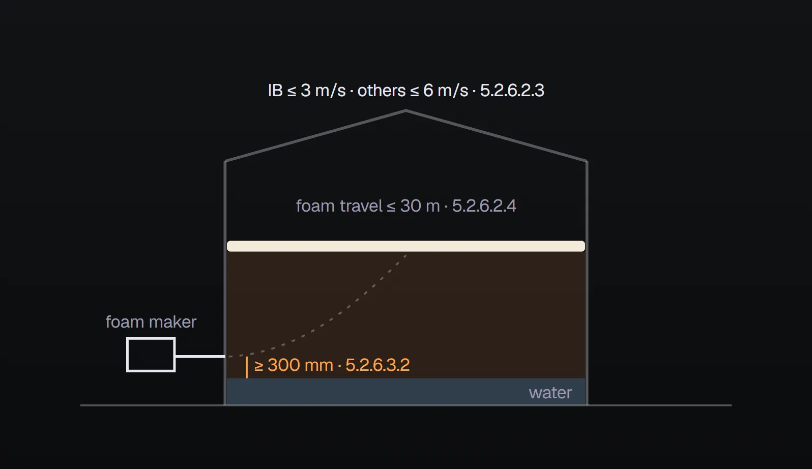
| Subsurface injection | Foam discharged into a tank from an outlet near the bottom. | 3.3.14.2 |
| Semi-subsurface injection | Foam released at the liquid surface by a floating hose rising from a piped container near the bottom. | 3.3.14.1 |
| Low-level outlet | Not defined in Chapter 3; described in 5.7.3.5.1 (see below). | 5.7.3.5.1 |
Fixed-roof tanks: where the Type II outlet goes
On a vertical fixed-roof (cone) atmospheric tank the outlets are attached to the tank (5.2.5.1.1). The aim is an outlet that survives the initial explosion and keeps the tank contents out of its own line:
- At the top of the shell, located or connected so that the contents cannot overflow into the foam lines (5.2.5.1.3).
- Two or more outlets are spaced equally around the periphery (5.2.5.1.2), individually piped and valved for isolation outside the dike (5.2.5.1.2.1), each delivering the minimum rate on its own (5.2.5.1.2.2).
- Attached so that displacement of the roof will not damage it (5.2.5.1.4).
- A seal frangible under low pressure keeps vapours out (5.2.5.1.5), with inspection access to replace it (5.2.5.1.6).
The number of outlets comes from tank diameter in Table 5.2.5.2.1, and rate and time from Table 5.2.5.2.2. For hydrocarbons with Type II outlets the minimum rate is 4.1 mm/min (0.10 gpm/ft²). Those tables and a worked example are in NFPA 11 fixed-roof tank foam. Fixed outlets are not used on horizontal or pressure tanks (5.2.3).
Subsurface outlets: foam rises through the fuel
Here foam rises through the fuel from near the tank bottom. NFPA 11 permits it for liquid hydrocarbons in vertical fixed-roof atmospheric tanks (5.2.6.1). It is not used for Class IA hydrocarbons or for alcohols, esters, ketones, aldehydes, anhydrides and other products that need alcohol-resistant foam (5.2.6.1.1). Concentrates and equipment must be listed for the purpose (5.2.6.1.2).
- The outlet may be the open end of a foam delivery line or a product line (5.2.6.2.1), sized so that the foam maker's discharge pressure and the velocity limits are not exceeded (5.2.6.2.2).
- Foam entering the tank contents may not exceed 3 m/s (10 ft/s) for Class IB liquids or 6 m/s (20 ft/s) for other classes, unless actual tests prove higher velocities satisfactory (5.2.6.2.3).
- With two or more outlets, foam travel on the surface cannot exceed 30 m (100 ft) (5.2.6.2.4), and each outlet delivers the minimum rate on its own (5.2.6.2.5).
- Outlets may be separate shell connections or a manifold inside the tank fed from one shell connection (5.2.6.2.6); manway covers may be used instead of new nozzles (5.2.6.2.7).
- The outlet must not discharge into a water bottom: it sits at least 300 mm (12 in.) above the highest water level (5.2.6.3.1, 5.2.6.3.2).
- Pipe sizes and lengths beyond the foam maker and the maximum fuel depth must keep back pressure within the device's tested and listed range (5.2.6.4).
The outlet count depends on flash point (Table 5.2.6.2.8): over 24 to 37 m needs 2 outlets below 38 °C and 1 at 38 °C or higher. The minimum rate is 4.1 mm/min, capped at 8.1 mm/min (0.20 gpm/ft²) by a table note (Table 5.2.6.5.1). See NFPA 11 subsurface foam injection.
Semi-subsurface
Here a floating hose releases foam at the surface, so it does not pass through the fuel (3.3.14.1). NFPA 11 gives no rate table for it; all equipment must be listed or approved for the purpose (5.2.7), so design values come from the listing.
Floating-roof tanks: outlets aimed at the seal
On an open-top floating-roof tank the outlets target the seal area. Foam goes either above the mechanical shoe seal, metal weather shield or secondary seal, or below them: onto the liquid, the tube seal envelope or the primary seal (5.3.5.1). With the top-of-seal method the outlets are used together with a foam dam (5.3.5.2.1). They may be mounted above the top of the tank shell (normally Type II) or on the periphery of the floating roof (5.3.5.2.2).
Unlike fixed-roof outlets (5.2.5.1.5), these outlets are not fitted with a frangible vapour seal (5.3.5.2.3). For top-of-seal systems Table 5.3.5.3.1 gives 12.2 mm/min (0.3 gpm/ft²) for 20 minutes for all four seal types, with outlets at most 12.2 m (40 ft) apart behind a 305 mm (12 in.) foam dam or 24.4 m (80 ft) behind a 600 mm (24 in.) dam. See NFPA 11 floating-roof seal protection.
Low-level outlets in dikes
In a diked spill fire foam is delivered from ground level. A low-level outlet is an open pipe fitting or directional nozzle sending a compact, low-velocity stream onto the inner dike wall or, where necessary, the floor (5.7.3.5.1). Outlets go around the dike wall and, if needed, inside it, for uniform coverage (5.7.3.5.2). As primary protection, their spacing depends on the outlet flow:
- At 230 L/min (60 gpm) or less per outlet, no point in the dike may be more than 9 m (30 ft) from an outlet (5.7.3.5.3.1).
- Above 230 L/min per outlet, outlets are at most 18 m (60 ft) apart (5.7.3.5.3.2).
Table 5.7.3.2 gives low-level outlets 4.1 mm/min (0.10 gpm/ft²) for 30 minutes on Class I and 20 minutes on Class II hydrocarbons; monitors need 6.5 mm/min (0.16 gpm/ft²) for the same times. Monitors stand outside the dike (5.7.3.5.4), and a compact, high-velocity stream is aimed at walls or tank surfaces so it does not plunge into the burning liquid (5.7.3.5.4.2). See NFPA 11 dikes, spill areas and loading racks.
Monitors and handlines: foam thrown from outside
Monitor and handline foam travels through the air, so the calculation allows for wind and ambient losses with an additional factor of at least 1.5 on the application rate (5.2.4.2.1.1, 5.2.4.2.1.2). For a fixed-roof hydrocarbon tank Table 5.2.4.2.2 gives 6.5 mm/min (0.16 gpm/ft²) for 50 or 65 minutes. A monitor can be primary protection for a cone-roof tank only within a system that can be in service within 4 hours, with a risk assessment, a pre-incident plan and AHJ approval (5.2.4.1.1). Handlines cannot be primary protection on a fixed-roof tank over 9 m (30 ft) in diameter or 6.1 m (20 ft) high (5.2.4.1.2). See NFPA 11 supplementary hose streams and monitors.
Side-by-side comparison
| Outlet | Location | How foam reaches the surface | Governing values | Clause |
|---|---|---|---|---|
| Type II fixed outlet (fixed roof) | Top of shell | Delivered onto the surface, limited submergence | 4.1 mm/min; 30 / 55 min; count from Table 5.2.5.2.1; frangible vapour seal | 5.2.5 |
| Subsurface | Near the bottom, at least 300 mm above the highest water level | Rises through the fuel | Velocity ≤ 3 m/s (IB), ≤ 6 m/s (others); travel ≤ 30 m; 4.1–8.1 mm/min | 5.2.6 |
| Semi-subsurface | Bottom container and floating hose | Hose releases foam at the surface | Listed or approved equipment | 5.2.7 |
| Floating-roof seal outlet | Above the shell top or on the roof periphery | Into the seal ring held by a foam dam | 12.2 mm/min; 20 min; spacing 12.2 / 24.4 m; no frangible seal | 5.3.5 |
| Low-level outlet | Around the dike wall, inside if needed | Runs down the inner wall and across the floor | 4.1 mm/min; 30 / 20 min; 9 m reach or 18 m spacing | 5.7.3.5 |
| Monitor / handline | Outside the tank or dike | Thrown through the air, aimed at a wall | Factor of at least 1.5; fixed roof 6.5 mm/min, 50 / 65 min | 5.2.4, 5.7.3.5.4 |
To test rate and time for a tank, use the NFPA 11 design criteria calculator.
Frequently Asked Questions
What is the difference between Type I and Type II foam outlets in NFPA 11?
A Type I outlet conducts foam onto the liquid surface so as to reduce submergence and surface agitation (3.3.3.2). A Type II outlet delivers foam onto the burning surface, partly submerging it while restricting fuel agitation (3.3.3.3). The fixed-roof tank table is written for Type II outlets (Table 5.2.5.2.2).
Is a foam chamber the same as a fixed foam discharge outlet?
Yes. NFPA 11-2024 does not define foam chamber separately; it refers the reader to the definition of fixed foam discharge outlet (3.3.10, 3.3.3.1).
What foam velocity limit applies to subsurface injection?
At the point of entry into the tank contents, foam velocity may not exceed 3 m/s (10 ft/s) for Class IB liquids or 6 m/s (20 ft/s) for other classes, unless actual tests prove higher velocities satisfactory (5.2.6.2.3).
Do floating-roof seal outlets have a vapour seal?
No. For top-of-seal application the fixed foam outlets are not fitted with a frangible vapour seal (5.3.5.2.3). The frangible seal is required on fixed-roof tank outlets (5.2.5.1.5).
How far apart are low-level foam outlets in a dike?
At 230 L/min or less per outlet, no point in the dike may be more than 9 m from an outlet (5.7.3.5.3.1). Above 230 L/min, the maximum distance between outlets is 18 m (5.7.3.5.3.2).

SprinkCalc — Fire Sprinkler Design Across Three Standards
SprinkCalc covers hazard classification, design density and area, K-factor selection, water demand and hydraulic calculations for NFPA 13, FM Global and BS EN 12845 in a single iOS app, and exports a professional PDF report.
Download SprinkCalc on the App Store
MEP Calc — 110+ Engineering Calculators
MEP Calc bundles 110+ engineering modules in one iOS app: 21 fire calculations plus heating, cooling, HVAC, plumbing, steam and natural gas.
Download MEP Calc on the App StoreNFPA 11, Standard for Low-, Medium-, and High-Expansion Foam, 2024 edition: 3.3.3–3.3.3.4, 3.3.10, 3.3.14 (pp. 11-10, 11-11); 3.3.19, 3.3.23–3.3.25, 3.3.31 (p. 11-12); 5.2, 5.2.3 (p. 11-18); 5.2.4.1–5.2.4.2, Table 5.2.4.2.2, 5.2.5.1 (p. 11-19); Table 5.2.5.2.1, 5.2.6.1–5.2.6.4 (p. 11-20); Table 5.2.6.2.8, Table 5.2.6.5.1, 5.2.7 (p. 11-21); 5.3.5.1–5.3.5.2.3, Table 5.3.5.3.1 (p. 11-23); Table 5.7.3.2, 5.7.3.5 (p. 11-28). Values were read from images of the standard's PDF pages. The binding text is the standard itself and the decision of the authority having jurisdiction.