How a foam system is built on site is agreed on paper first. NFPA 11-2024 collects that paper side in Chapter 9, "Specifications and Plans". The chapter is short, but it defines the file that approval, installation and acceptance all rest on. Working plans for foam-water sprinkler and spray systems (6.3) and plans and specifications for compressed air foam systems (8.18) also point to it.
Acceptance testing is covered in NFPA 11 Acceptance Tests and installation steps in Foam System Installation. This page is about the file itself: who prepares it, when it goes for approval and what it contains. Clause numbers were read from page images of the 2024 edition. For marine systems, Chapter 9 does not apply unless specifically referenced (11.1.2).
Approval sequence (9.1, 6.2.6)
Plans go to the authority having jurisdiction for approval before installation, or before an existing system is modified (9.1). Deviating from approved plans needs the AHJ’s permission (9.1.1). The foam-water sprinkler and spray chapter moves the conversation even earlier: the AHJ is consulted before the system is designed (6.2.6.1). All plans and specifications are approved before installation, and the AHJ is consulted on devices, materials and the choice of concentrate (6.2.6.2). Equipment and concentrate are approved for the intended application (6.2.6.3).
Annex A.9.1 (explanatory) calls it good practice for the owner or a representative to review the basic hazard or modification with the AHJ and obtain preliminary approval of the protection concept. Damage the agent itself might cause is part of the choice; where foam contamination could add substantially to the loss, as with edible oil tanks, the type of agent is discussed with the AHJ.
Specifications (9.2)
Specifications are written for every foam system and include at least three things (9.2):
- Who the AHJ is, and whether plans must be submitted (9.2.1).
- That the installation conforms to this standard and meets the AHJ’s approval (9.2.2).
- The specific tests the AHJ requires for approval (9.2.3).
Annex A.9.2.3 (explanatory) asks that the cost of tests beyond the standard but requested by the AHJ be considered, and that the specification say how that cost is met. It settles the “who pays for this test” question long before acceptance day.
Plans: who draws them and how (9.3.1, 9.3.2)
Only fully experienced and responsible people prepare plans (9.3.1). Sheets are drawn to an indicated scale or dimensioned (9.3.2), and every sheet carries a graphic scale (9.3.3(15)).
The 33 items on the plans (9.3.3)
9.3.3 lists, where applicable, 33 items of information that the plans include or that accompany them. The animation fills the file section by section; in the third section you can tap each of the 33 items to read it.
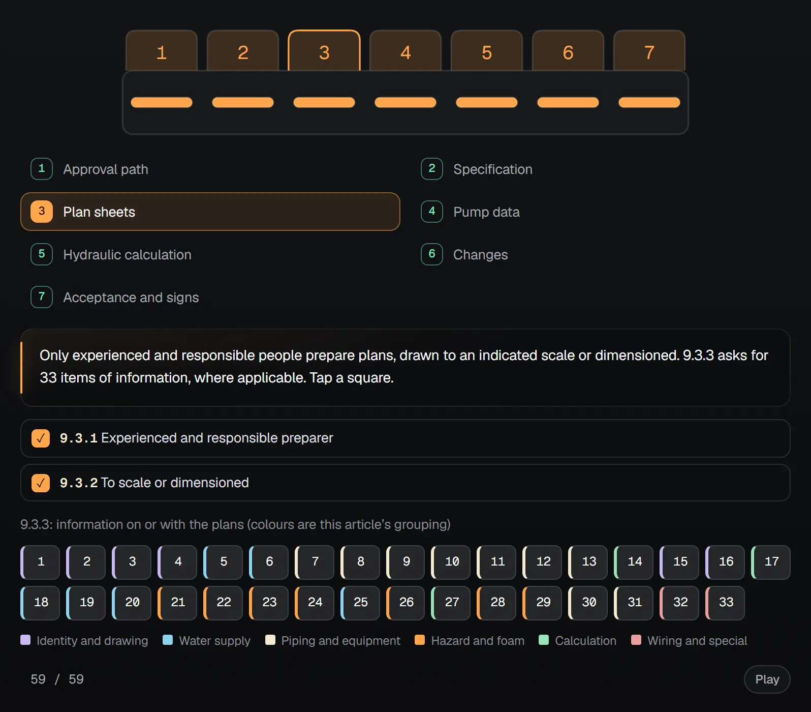
To make the list easier to read we sorted it into six groups (the grouping is ours):
- Identity and drawing: owner and occupant, street address, point of compass, full-height section or schematic including dike and tank construction, graphic scale, contractor name and address (1 to 4, 15, 16).
- Water supply: supply main size, dead end or circulating, flow test results and elevation relative to the test hydrant; other water sources; backflow preventers; hydrants, including the static and residual hydrants used in the test; fire department connections; water requirements (5, 6, 18 to 20, 25).
- Piping and equipment: make and model of discharge devices, pipe type and schedule, nominal sizes and cutting lengths, fittings, welds and bends, hangers and braces, valves, drains and test connections, flushing provisions, capacity and location of all equipment (7 to 13, 30, 31).
- Hazard and foam: physical details of the hazard, concentrate type and percentage, required solution rate, submergence volume, concentrate quantity, required air quantity and the compressed air foam flow report (21 to 24, 26, 28, 29).
- Calculation: hydraulic data nameplate information, reference points that match the calculation sheets, and the hydraulic calculations (14, 17, 27). Annex A.9.3.3(27) (explanatory) points to NFPA 13 Chapter 23 for the procedure; NFPA 11 leaves the method there.
- Wiring and special: schematic wiring diagram and explanation of special features (32, 33).
“Where applicable” matters: submergence volume, air quantity or a compressed air foam report do not apply to every system. But the file should make clear why an item is left blank.
Pump data (9.3.4, 9.3.6)
Complete plans and data for pumps, drivers, controllers, power supply, fittings, suction and discharge connections and suction conditions are submitted by the engineer or contractor for AHJ approval before installation (9.3.4). The contractor furnishes head, delivery, efficiency and brake horsepower curves for the pumps (9.3.6).
Hydraulic calculation forms (9.3.7)
Calculations are prepared on three forms: a summary sheet, detailed worksheets and a graph sheet (9.3.7.1).
- Summary sheet (9.3.7.2): date, location, owner, building number, hazard description, contractor or designer, approving authority; design requirements (application area, minimum rate, application per outlet, area per chamber or device, duration); total foam demand with inside hose, outside hydrant and exposure allowances; actual discharge conditions; and the allowable flow range of each proportioner. Annex A.9.3.7.2(10) (explanatory) notes that actual discharge conditions come from the calculation balanced to the available supply.
- Detailed worksheets (9.3.7.3): sheet number, device description and K-factor, reference points, flow, pipe size and lengths, equivalent lengths of fittings, friction loss per metre and in total, elevation head, required pressure at each point, velocity pressure where used, and explanatory notes.
- Graph sheet (9.3.7.4): on Q1.85 paper, the water supply curve, the foam system demand and any hose allowance.
- Water supply analysis (9.3.7.5): node tag at the source, static and residual pressure, available flow, pressure available with the total demand flowing, total calculated demand, pressure required for it, total flow balanced to the supply and the balanced pressure.
Changes on site (9.1.1, 9.3.5)
If field conditions force a change affecting system performance, revised “as installed” plans go to the AHJ for approval (9.3.5). Any deviation from approved plans needs permission (9.1.1). By acceptance day the file and the site should match, because that is the first thing the inspection compares.
Ready for acceptance, and signs (12.1 and Chapter 4)
At acceptance the system is checked by eye against the approved plans and specifications (12.1.1). The inspection covers conformity with the installation plans, pipe continuity, removal of temporary blinds, access to valves, controls and gauges, and correct vapour seals where fitted (12.1.2). Devices are checked for identification and operating instructions (12.1.3). Some of the markings the file should define:
- A sign on the proportioning system giving the correct shutdown sequence, to avoid losing concentrate or damaging the system (4.3.2.3.1.3).
- Permanent marking of orifice diameter, and of flow direction where it matters, on the orifice plate tab or nameplate (4.5.2.4).
- A permanent weatherproof sign with the set pressure of any pressure-reducing deluge valve (4.7.6.6).
- The general information sign for foam-water deluge and spray systems (12.9.7), covered in the acceptance tests article.
Checklist
| Clause | What the file holds | When |
|---|---|---|
| 6.2.6.1 | Record of consulting the AHJ before design | Before design |
| 6.2.6.2, 6.2.6.3 | Devices, materials and concentrate discussed with the AHJ; approvals for the application | During design |
| 9.2.1 | AHJ named; whether plans must be submitted | Specification |
| 9.2.2 | Conformity with the standard and AHJ approval | Specification |
| 9.2.3 | Specific tests required by the AHJ (Annex A.9.2.3: how costs are met) | Specification |
| 9.3.1 | Experienced, responsible preparer | Plans |
| 9.3.2, 9.3.3(15) | Scale or dimensions; graphic scale on every sheet | Plans |
| 9.3.3(1) to (33) | The 33 items, where applicable | Plans |
| 9.1 | Plans submitted before installation or modification | Before installation |
| 9.3.4 | Pump, driver, controller, power and suction data | Before installation |
| 9.3.6 | Pump curves: head, delivery, efficiency, brake horsepower | Before installation |
| 9.3.7.1 to 9.3.7.5 | Summary, worksheets, Q1.85 graph, water supply analysis | With plans |
| 9.1.1 | AHJ permission for each deviation | During installation |
| 9.3.5 | Revised “as installed” plans for changes affecting performance | End of installation |
| 12.1.1 to 12.1.3 | Visual check against approved plans; device identification and instructions | Acceptance |
| 4.3.2.3.1.3 | Shutdown sequence sign on the proportioning system | Before acceptance |
| 4.5.2.4, 4.7.6.6 | Orifice plate marking; set-pressure sign | Before acceptance |
Questions before handing over the file. Does the specification name the AHJ and list the special tests (9.2.1, 9.2.3)? Do the reference points on the plans match the calculation sheets (9.3.3(17))? Is each proportioner’s allowable flow range on the summary sheet (9.3.7.2(11))? Did pump curves and suction conditions go for approval (9.3.4, 9.3.6)? Are site changes shown on revised plans (9.3.5)?
For the numbers, use the NFPA 11 Design Criteria Calculator; for choosing a system, see the Foam System Design Guide.
Frequently Asked Questions
When are foam system plans submitted under NFPA 11?
Before installation, or before an existing system is modified (9.1). For foam-water sprinkler and spray systems the AHJ is also consulted before design, and all plans and specifications are approved before installation (6.2.6.1, 6.2.6.2).
What information must foam system plans contain?
Clause 9.3.3 lists 33 items where applicable: identity and location, water supply and flow test, piping, fittings and hangers, valves and test connections, hazard details, concentrate type and percentage, solution rate, water and concentrate quantities, hydraulic calculations, equipment capacities, wiring diagram and special features.
Which forms make up an NFPA 11 hydraulic calculation?
A summary sheet, detailed worksheets and a Q^1.85 graph sheet (9.3.7.1), plus a water supply analysis (9.3.7.5). The summary sheet also gives each proportioner’s allowable flow range (9.3.7.2(11)).
What happens if the site needs a change from the approved plans?
Any deviation needs AHJ permission (9.1.1). If the change affects system performance, revised “as installed” plans are submitted for approval (9.3.5).
Does NFPA 11 Chapter 9 apply to marine foam systems?
Not unless specifically referenced. Under Chapter 11, Chapters 4, 5, 7 and 9 do not apply to marine systems (11.1.2).

SprinkCalc — Fire Sprinkler Design Across Three Standards
SprinkCalc covers hazard classification, design density and area, K-factor selection, water demand and hydraulic calculations for NFPA 13, FM Global and BS EN 12845 in a single iOS app, and exports a professional PDF report.
Download SprinkCalc on the App Store
MEP Calc — 110+ Engineering Calculators
MEP Calc bundles 110+ engineering modules in one iOS app: 21 fire calculations plus heating, cooling, HVAC, plumbing, steam and natural gas.
Download MEP Calc on the App StoreNFPA 11, Standard for Low-, Medium-, and High-Expansion Foam, 2024 edition: 4.3.2.3.1.3 (p. 11-14); 4.5.2.4 (p. 11-15); 4.7.6.6 (p. 11-18); 6.2.6, 6.3 (p. 11-30); 8.18 and 9.1 to 9.3.3(10) (p. 11-44); 9.3.3(11) to 9.3.7.5 (p. 11-45); 11.1.2 (p. 11-47); 12.1 (p. 11-51); 12.9.7 (p. 11-56); Annex A (explanatory): A.9.1 (p. 11-98), A.9.2.3, A.9.3.3(27), A.9.3.7.2(10) (p. 11-99). No source other than NFPA 11 was used; NFPA 13 is named only as the document Annex A points to. The grouping of the 9.3.3 items is this page’s own. The binding text is the standard itself and the decision of the authority having jurisdiction.