A diesel fire pump room also carries the engine’s combustion and cooling air. NFPA 20-2025 Section 11.3 covers the floor pitch, alternate power and ventilation of this room. Separation, heating, drainage and lighting of the room are summarized in the pump room article; this article focuses on diesel room ventilation and the design guidance in Annex A.
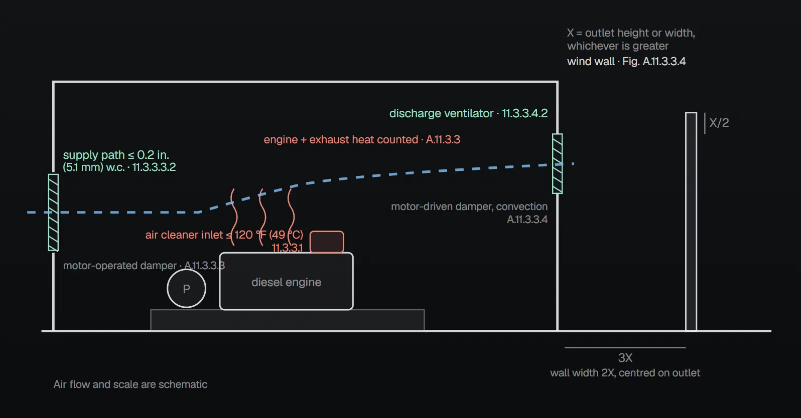
In short: ventilation does four jobs: it limits the combustion air cleaner inlet to 120 °F (49 °C) with the engine at rated load, supplies combustion air, removes hazardous vapors and, where needed, supplies and exhausts radiator air (11.3.3.1). The total supply path restricts air flow by no more than 0.2 in. (5.1 mm) water column, and for radiator-cooled engines the discharge path by no more than 0.3 in. (7.6 mm) (11.3.3.3.2, 11.3.3.4.3.3). Where these functions rely on power and the normal source is unreliable, alternate power is provided (11.3.2).
What the rules say
- The floor around the pump and engine is pitched to drain escaping water away from critical equipment such as the pump, engine, controller and fuel tank (11.3.1).
- Where a requirement of Section 11.3 relies on a power source and the normal source is unreliable, an alternate source is provided for those electrically operated components (11.3.2). Annex A.11.3.2 gives electrically operated ventilation and unit heaters in the pump room as examples and points to Annex A.9.3.1(1) for judging an unreliable source.
- Ventilation system components are coordinated with engine operation (11.3.3.2).
| Air path | Includes | Limit | Paragraph |
|---|---|---|---|
| Air supply ventilator | Anything in the air supply path to the room | Total restriction no more than 0.2 in. (5.1 mm) water column | 11.3.3.3.1, 11.3.3.3.2 |
| Air discharge ventilator | Anything in the discharge path from the engine to the outdoors | Lets enough air leave the room to satisfy 11.3.3 | 11.3.3.4.1, 11.3.3.4.2 |
| Radiator-cooled engine discharge | Radiator discharge ducted outdoors so as to prevent recirculation; duct attached to the radiator through a flexible section | Discharge path no more than 0.3 in. (7.6 mm) water column | 11.3.3.4.3.1–11.3.3.4.3.3 |
The radiator fan, in turn, is capable of a 0.5 in. (13 mm) water column restriction created by the combination of the supply and discharge ventilators plus the radiator, fan guard and other engine component obstructions (11.2.8.8.4.2); the cooling side is in the cooling and lubrication article.
Cold-weather recirculation duct
A recirculation duct is permitted for cold-weather operation when (11.3.3.4.3.4):
- The recirculated airflow is regulated by a thermostatically controlled damper.
- The control damper fully closes in a failure mode.
- The recirculated air is ducted to prevent direct recirculation to the radiator.
- The duct does not raise the temperature at the combustion air cleaner inlet above 120 °F (49 °C).
- The bypass supplies air to the room when needed and when the damper is open, and does not exhaust air from the room.
Annex A.11.3.3.4.3.4 explains the last item: an improperly installed bypass duct can draw air rather than supply it, due to venturi effect.
Annex A design guidance
| Topic | Guidance | Source |
|---|---|---|
| Ventilator location | Supply and discharge on opposite walls | A.11.3.3 |
| Room temperature calculation | Radiated heat from the engine and exhaust piping and all other heat sources are considered; engine combustion air counts as part of the room air changes | A.11.3.3 |
| Power ventilator | Reliability of its power source during a fire is considered; if unreliable, the temperature rise is calculated assuming the ventilator does not operate | A.11.3.3 |
| Heat exchanger–cooled engine | Engine air consumption is typically not enough, so additional air flow is needed; motor-operated dampers to enhance convection; on discharge, a convection ventilator with motor-driven dampers preferred over a power ventilator (larger, but not dependent on power) | A.11.3.3, A.11.3.3.3, A.11.3.3.4 |
| Radiator-cooled engine | Radiator discharge and engine consumption could give sufficient air changes; gravity-operated dampers to simplify coordination with the fan; louvers and motor-operated dampers not recommended | A.11.3.3, A.11.3.3.3, A.11.3.3.4 |
| Motor-operated dampers | Spring operated to open, motored closed, signaled to open when or before the engine begins cranking | A.11.3.3.3, A.11.3.3.4 |
| Passive duct instead of dampers | A vent duct with rain cap through the roof or outside wall, its bottom about 6 in. (152.4 mm) off the floor; reduces winter heat loss; sized to meet 11.3.3.1 | A.11.3.3.3 |
| Prevailing winds | Can work against the discharge ventilator and are considered when locating it; recommended wind wall in Figure A.11.3.3.4 | A.11.3.3.4 |
In Figure A.11.3.3.4, X is the outlet height or width, whichever is greater: the wind wall stands 3X from the outlet, rises X/2 above the top of the outlet, is 2X wide and is centred on the outlet. The duct example in the Annex A.11.3.3 figures shows that if a bend in the radiator ducting cannot be avoided it is radiused and fitted with turning vanes; a sharp-turn duct right at the radiator is not used because turbulence will not allow adequate air flow.
Why?
- Reliable power: the NFPA 20 Handbook (2022) commentary notes that during a fire the utility typically opens the feeder to the facility; if ventilation depends on that power the room will likely overheat and engine performance suffers. A means is needed to keep the room ventilated in an emergency.
- Restriction limits: the Handbook (2022) says the limits keep the room from operating at a pressure that could compromise engine performance or overheat a radiator-cooled system. Annex A.11.3.3.3 and A.11.3.3.4 tie the limits to compatibility with listed engines for adequate cooling and combustion air; on the supply side the restriction includes louvers, bird screens, dampers, ducts and anything else between the room and the outdoors.
- Room location: Annex A.11.3 notes the engine-driven pump can share a pump house or room with electric-driven pumps, and that room should be entirely cut off from the main structure by noncombustible construction.
Mistakes named in the sources
- Leaving ventilation or heaters on an unreliable utility supply (11.3.2; Handbook 2022 commentary).
- A sharp turn in the radiator discharge duct: the Annex A figure marks this arrangement “wrong”.
- Louvers or motor-operated dampers with a radiator-cooled engine: Annex A.11.3.3.4 does not recommend them because of the restriction they create and the air pressure they must work against.
- A recirculation bypass that draws air from the room (11.3.3.4.3.4(5), A.11.3.3.4.3.4).
Checklist
- Does ventilation meet the four functions of 11.3.3.1, with the air cleaner inlet at no more than 120 °F (49 °C) at rated load?
- Is the total supply path restriction no more than 0.2 in. (5.1 mm) water column? (11.3.3.3.2)
- For a radiator-cooled engine, is the duct outdoors, with a flexible section and no more than 0.3 in. (7.6 mm)? (11.3.3.4.3)
- Are dampers coordinated with the engine, and do motor-operated dampers open at cranking? (11.3.3.2, A.11.3.3.3)
- Is there alternate power for electric ventilation and heaters where the normal source is unreliable? (11.3.2)
- Is the floor pitched away from critical equipment? (11.3.1)
Frequently Asked Questions
What does ventilation do in a diesel pump room?
Under NFPA 20-2025 11.3.3.1 it has four functions: keep the combustion air cleaner inlet at no more than 120 °F (49 °C) with the engine at rated load, supply combustion air, remove hazardous vapors and supply and exhaust air for radiator cooling when required.
What are the air path restriction limits?
The total air supply path to the room restricts air flow by no more than 0.2 in. (5.1 mm) water column (11.3.3.3.2). For radiator-cooled engines the discharge path restricts it by no more than 0.3 in. (7.6 mm) water column (11.3.3.4.3.3).
Which dampers suit a radiator-cooled engine?
Annex A.11.3.3.3 and A.11.3.3.4 recommend gravity-operated dampers to simplify coordination with the fan; louvers and motor-operated dampers are not recommended because of the restriction they create and the air pressure they must work against.
Can radiator air be recirculated in cold weather?
Yes, under 11.3.3.4.3.4: a thermostatic damper, full closure on failure, no direct return to the radiator, no rise above 120 °F (49 °C) at the air cleaner inlet and a bypass that does not exhaust air from the room.
What if ventilation fans lose power?
Where a requirement of Section 11.3 relies on a power source and the normal source is unreliable, alternate power is provided (11.3.2). Annex A.11.3.3 recommends calculating the temperature rise as if the power ventilator does not operate when its source is unreliable.

SprinkCalc — Fire Sprinkler Design Across Three Standards
SprinkCalc covers hazard classification, design density and area, K-factor selection, water demand and hydraulic calculations for NFPA 13, FM Global and BS EN 12845 in a single iOS app, and exports a professional PDF report.
Download SprinkCalc on the App Store
MEP Calc — 110+ Engineering Calculators
MEP Calc bundles 110+ engineering modules in one iOS app: 21 fire calculations plus heating, cooling, HVAC, plumbing, steam and natural gas.
Download MEP Calc on the App StoreNFPA 20-2025, Standard for the Installation of Stationary Pumps for Fire Protection: 11.2.8.8.4.2; 11.3.1; 11.3.2; 11.3.3.1–11.3.3.4.3.4; Annex A.11.3, A.11.3.2, A.11.3.3, A.11.3.3.3, A.11.3.3.4, A.11.3.3.4.3.4 and the Annex A.11.3.3 and A.11.3.3.4 figures (explanatory). NFPA 20 Handbook 2022 commentary: Section 11.3.