A diesel fire pump engine is cooled either by a heat exchanger fed with the pump’s own water or by a radiator with air pushed by the engine fan. NFPA 20-2025 covers cooling in 11.2.8 and lubrication in 11.2.9. Reasons are taken only from Annex A and the NFPA 20 Handbook (2022) commentary.
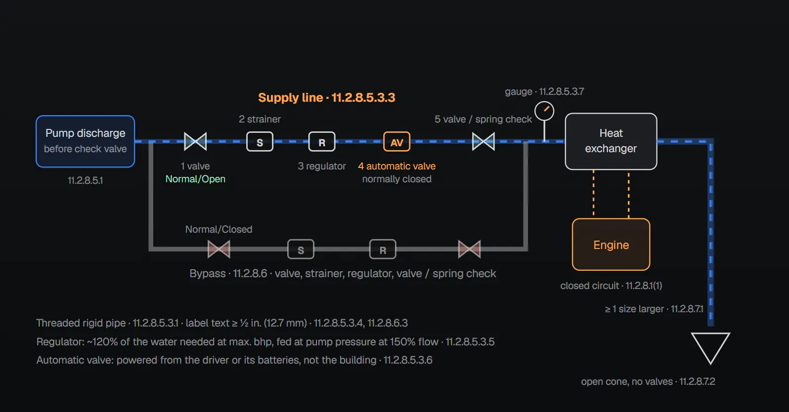
In short: The cooling system is part of the engine assembly and is a closed-circuit heat exchanger or radiator type (11.2.8.1). Heat exchanger water is taken from the pump discharge before the discharge check valve (11.2.8.5.1); in the direction of flow the line has an indicating valve, strainer, pressure regulator, automatic valve and a second valve or spring-loaded check valve (11.2.8.5.3.3), with a bypass around it (11.2.8.6). The waste outlet line is at least one size larger than the inlet, has no valves and discharges into an open cone (11.2.8.7). Radiators are designed for 120 °F (49 °C) inlet air (11.2.8.8.2). Oil heaters follow the engine maker’s recommendations (11.2.9.1).
Cooling type
- Heat exchanger type: engine-driven circulating pump, heat exchanger and engine jacket temperature regulating device (11.2.8.1(1)).
- Radiator type: engine-driven circulating pump, radiator, jacket temperature regulating device and an engine-driven fan for positive air movement through the radiator (11.2.8.1(2)).
- A means maintains 120 °F (49 °C) at the combustion chamber (11.2.8.2); this rule also appears in the pump room article. The circuit has an opening for filling, level checks and make-up; coolant follows the engine maker’s recommendation (11.2.8.3, 11.2.8.4).
Heat exchanger water supply
Water comes from the pump discharge, before the discharge check valve; the required flow is set for the maximum ambient cooling water temperature (11.2.8.5.1, 11.2.8.5.2). The connection is threaded rigid pipe (11.2.8.5.3.1). Nonmetallic flexible sections are allowed between the pump discharge and the assembly inlet and between the assembly outlet and the engine inlet if rated for at least 2 times the pump discharge rated pressure with a 30-minute fire resistance equal to ISO 15540 (11.2.8.5.3.2).
| Order (direction of flow) | Component and rule | Section |
|---|---|---|
| 1 | Indicating manual shutoff valve; permanent label with text at least ½ in. (12.7 mm): “Normal/Open” in the normal position, “Caution: Nonautomatic/Closed” for emergency or manual position | 11.2.8.5.3.3, 11.2.8.5.3.4 |
| 2 | Approved flushing-type strainer (in addition to any in the regulator) | 11.2.8.5.3.3 |
| 3 | Pressure regulator sized and set to pass about 120% of the cooling water needed at maximum brake horsepower, when supplied at pump pressure at 150% of rated capacity | 11.2.8.5.3.5 |
| 4 | Automatic valve: listed for fire protection service, opens when the engine runs, powered from the diesel driver or its batteries (not the building), normally closed; not required on a vertical turbine pump or any pump with no discharge pressure when idle | 11.2.8.5.3.6 |
| 5 | Second indicating manual shutoff valve or a spring-loaded check valve | 11.2.8.5.3.3 |
| Gauge | On the engine side of the last valve in the supply and bypass lines | 11.2.8.5.3.7 |
Where the AHJ requires two levels of separation from the ground or potable water source, dual spring-loaded check valves or backflow preventers are installed: the check valve replaces the second manual valve; backflow preventers are listed for fire protection service and installed in parallel in the supply and bypass assemblies; because of the added pressure loss, cooling loop pipe size is documented by engineering calculations (11.2.8.5.3.8). Per the Handbook (2022), the reason is that antifreeze inhibitors could find their way back into the water supply.
Bypass line
A threaded rigid pipe bypass is installed around the heat exchanger water supply, with, in the direction of flow, an indicating manual valve, flushing-type strainer, pressure regulator and an indicating manual valve or spring-loaded check valve (11.2.8.6.1, 11.2.8.6.2). The bypass valve label reads “Normal/Closed” in the normal position and “Emergency/Open” for manual operation or when the engine is overheating (11.2.8.6.3). Per Annex A.11.2.8.6, where the water may carry wood chips, leaves, lint and similar material, the strainers should be duplex filters, each clean element good for full flow for 3 hours, with a same-size duplex filter in the bypass.
Waste outlet
- The discharge line is at least one size larger than the inlet line (11.2.8.7.1).
- It is as short as practical, discharges into a visible open waste cone and has no valves (11.2.8.7.2).
- It may discharge to a suction reservoir if a visual flow indicator and temperature indicator are installed (11.2.8.7.3).
- If longer than 15 ft (4.6 m) or discharging more than 4 ft (1.2 m) above the heat exchanger, the pipe is increased by at least one size (11.2.8.7.4).
Per the Handbook (2022), small engines may need only 12–15 gpm (45–57 L/min) and larger engines 200 gpm (760 L/min) or more; the actual flow comes from the engine maker’s data.
Radiator
- Heat is dissipated by air moved through the radiator by a fan included with, and driven by, the engine (11.2.8.8.1).
- The radiator limits maximum engine operating temperature with 120 °F (49 °C) inlet air at the combustion air cleaner inlet (11.2.8.8.2).
- It has a flange on the air discharge side for a flexible duct to the discharge air ventilator; the fan pushes air through the radiator and out through that ventilator (11.2.8.8.3, 11.2.8.8.4.1).
- The fan handles a 0.5 in. water column (13 mm water column) restriction from the supply and discharge ventilators plus radiator, fan guard and other obstructions, and is guarded for personnel protection (11.2.8.8.4.2, 11.2.8.8.4.3).
A radiator-cooled engine takes no cooling water from the pump discharge, so the 4.13.1.2 exception does not apply and a circulation relief valve is required (4.13.1, 4.13.1.2); see circulation relief valve. For room ventilation see diesel pump room ventilation.
Lubrication
The engine maker’s recommendations for oil heaters are followed (11.2.9.1). Per the Handbook (2022), some climates need an oil heater in the engine sump, supplied as part of the listed engine for the site climate.
Why?
- 120 °F: The Handbook (2022) says keeping the engine at 120 °F (49 °C) helps it start quickly and reach full speed within 20 seconds, and prevents condensation build-up.
- Regulators: Per the Handbook (2022), engine heat exchangers have low pressure limits of 15–60 psi (1–4.1 bar); the regulators in the supply and bypass reduce pump outlet pressure below that limit.
- Bypass: Per the Handbook (2022), the bypass keeps cooling water flowing even during maintenance of the main line; a falling gauge reading signals possible overheating.
- Flexible sections: The Handbook (2022) notes that nonmetallic flexible sections sometimes give a more reliable installation because of engine vibration.
Error noted in the sources
Handbook (2022): where a water storage tank supplies the system, verify that the automatic valve closes completely after the pump runs; if it fails to close, the tank can drain over time.
Checklist
- Cooling water taken before the discharge check valve, in threaded rigid pipe? (11.2.8.5.1, 11.2.8.5.3.1)
- Main line order correct, automatic valve normally closed? (11.2.8.5.3.3, 11.2.8.5.3.6)
- Bypass installed, valve labels with text at least ½ in. (12.7 mm)? (11.2.8.6)
- Waste line one size larger, valve-free, to an open cone? (11.2.8.7)
- On a radiator engine, fan rated for 0.5 in. wc (13 mm wc) and a circulation relief valve installed? (11.2.8.8.4.2, 4.13.1)
Frequently Asked Questions
Where is diesel engine cooling water taken from?
For a heat exchanger system, from the pump discharge before the discharge check valve (NFPA 20-2025 11.2.8.5.1). The connection is threaded rigid pipe (11.2.8.5.3.1).
What components are in the cooling water line, in what order?
In the direction of flow: indicating manual shutoff valve, flushing-type strainer, pressure regulator, automatic valve, and a second indicating valve or spring-loaded check valve (11.2.8.5.3.3). The gauge is on the engine side of the last valve (11.2.8.5.3.7).
How is the pressure regulator set?
It is sized and set to pass about 120% of the cooling water needed at maximum engine brake horsepower when supplied at pump pressure with the pump at 150% of rated capacity (11.2.8.5.3.5).
Can a valve be installed in the waste outlet line?
No. The line is as short as practical, discharges into a visible open cone and has no valves (11.2.8.7.2). It is at least one size larger than the inlet, and one more size if over 15 ft (4.6 m) long or discharging more than 4 ft (1.2 m) above the heat exchanger (11.2.8.7.1, 11.2.8.7.4).
What matters on a radiator-cooled diesel engine?
The radiator is designed for 120 °F (49 °C) inlet air and the fan handles a 0.5 in. water column (13 mm wc) restriction (11.2.8.8.2, 11.2.8.8.4.2). With no cooling water taken from the pump discharge, a circulation relief valve is required (4.13.1, 4.13.1.2).

SprinkCalc — Fire Sprinkler Design Across Three Standards
SprinkCalc covers hazard classification, design density and area, K-factor selection, water demand and hydraulic calculations for NFPA 13, FM Global and BS EN 12845 in a single iOS app, and exports a professional PDF report.
Download SprinkCalc on the App Store
MEP Calc — 110+ Engineering Calculators
MEP Calc bundles 110+ engineering modules in one iOS app: 21 fire calculations plus heating, cooling, HVAC, plumbing, steam and natural gas.
Download MEP Calc on the App StoreNFPA 20-2025, Standard for the Installation of Stationary Pumps for Fire Protection: 4.13.1, 4.13.1.2; 11.2.8.1–11.2.8.8.4.3; 11.2.9.1; Annex A.11.2.8.5, A.11.2.8.6, Figure A.11.2.8.5 (explanatory). NFPA 20 Handbook 2022 commentary: Sections 11.2.8, 11.2.9.