When a fire pump takes water from a pond, a wet pit or a tank, its intake faces two different hazards: material that can clog the pump, and a vortex that forms as the tank drains and carries air into the suction. NFPA 20-2025 answers the first with suction screening (4.16.8) and the second with an anti-vortex plate (4.16.10). Suction pipe size, elbow and reducer rules are covered in the suction pipe article; devices permitted in the suction line are covered in the valves and backflow preventer article.
In short: where water is taken from an open source such as a pond or wet pit, the passage of material that might clog the pump is obstructed (4.16.8.1) and double intake screens are provided (4.16.8.2). Below minimum water level the screens give an effective net opening of 1 in.² for each 1 gpm (170 mm² for each 1 L/min) at 150 percent of rated capacity (4.16.8.4), and the overall screen area is 1.6 times the net opening area (4.16.8.13). Where a tank is the suction source, its discharge outlet has an assembly that controls vortex flow in accordance with NFPA 22 (4.16.10).
Suction screening: what the rule says
- When: where the supply comes from an open source such as a pond or wet pit, the passage of materials that might clog the pump is obstructed (4.16.8.1).
- How many: double intake screens at the suction intake (4.16.8.2). Screens are removable or an in situ cleaning is provided (4.16.8.3), and they are arranged so they can be cleaned or repaired without disturbing the suction pipe (4.16.8.5).
- Net area: below minimum water level, an effective net opening of 1 in.² for each 1 gpm (170 mm² for each 1 L/min) at 150 percent of rated pump capacity (4.16.8.4).
- Overall area and open ratio: the overall screen area is 1.6 times the net screen opening area (4.16.8.13), with at least 62.5 percent open area (4.16.8.11).
- Mesh screens: brass, copper, nickel-copper alloy, stainless steel or other equivalent corrosion-resistant metal; mesh no larger than 0.50 in. (12.7 mm), wire No. 10 B&S gauge (4.16.8.6). Flat panel mesh is secured to a metal frame sliding vertically at the entrance to the intake (4.16.8.7).
- Continuous slot screens: the same materials, 0.125 in. (3.2 mm) maximum slot and profile wire construction (4.16.8.10).
- Screens in a sump: where located in a sump or depression, screens have a debris-lifting rake (4.16.8.8).
- Zebra mussels: where infestation is present or reasonably anticipated, screens are made of a material with demonstrated resistance to attachment, or coated with one that resists attachment at low velocities (4.16.8.12).
- Maintenance: the system is periodically test pumped, the screens removed for inspection and accumulated debris removed (4.16.8.9).
Example: screen area for a 750 gpm pump
From the NFPA 20 Handbook (2022) commentary: a 750 gpm (2839 L/min) vertical shaft turbine pump delivers 1125 gpm (4258 L/min) at 150 percent, so the net opening is 1125 in.² (0.72 m²). The overall screen area is 1.6 × 1125 = 1800 in.², that is 12.5 ft² or about 1.16 m² (4.16.8.4, 4.16.8.13).
Intake screen and suction strainer are different things
A vertical shaft turbine pump has a cast or heavy fabricated, corrosion-resistant metal cone or basket strainer attached to its suction manifold (7.3.4.1). Its free area is at least four times the area of the suction connections and its openings stop a 0.5 in. (12.7 mm) sphere (7.3.4.2); in a wet pit it is required in addition to the intake screen (7.3.4.3). On a horizontal pump, a suction strainer is permitted in the suction pipe only where another section of the standard requires it (4.16.9.2).
Why double screens and these materials?
Annex A.4.16.8 asks that screen material be chosen to prevent fouling from aquatic growth and notes that antifouling is best achieved with brass or copper wire. The NFPA 20 Handbook (2022) commentary explains the double screen: debris that settles in front of the intake is drawn onto the first screen when the pump runs in a fire, reducing the flow area; the second screen allows the first one to be removed if it becomes obstructed. Openings are kept small to protect the distribution system: the commentary’s example restricts them to less than ½ in. (12.7 mm) for a sprinkler with a ½ in. orifice.
On zebra mussels the same commentary notes that copper-based materials have been tested and proven resistant to attachment, pure copper only until corrosion products form on its surface, while some copper alloys, nickel-copper alloy and stainless steel showed no resistance. Materials that need regular maintenance to remove mussels should not be used.
Annex A.7.2.2.2 recommends that velocity in the approach channel or intake pipe not exceed approximately 2 ft/sec (0.7 m/sec) and in the wet pit approximately 1 ft/sec (0.3 m/sec); Figure A.7.2.2.2 shows the rack, the double screens and the pump strainer in a wet pit.
Anti-vortex plate
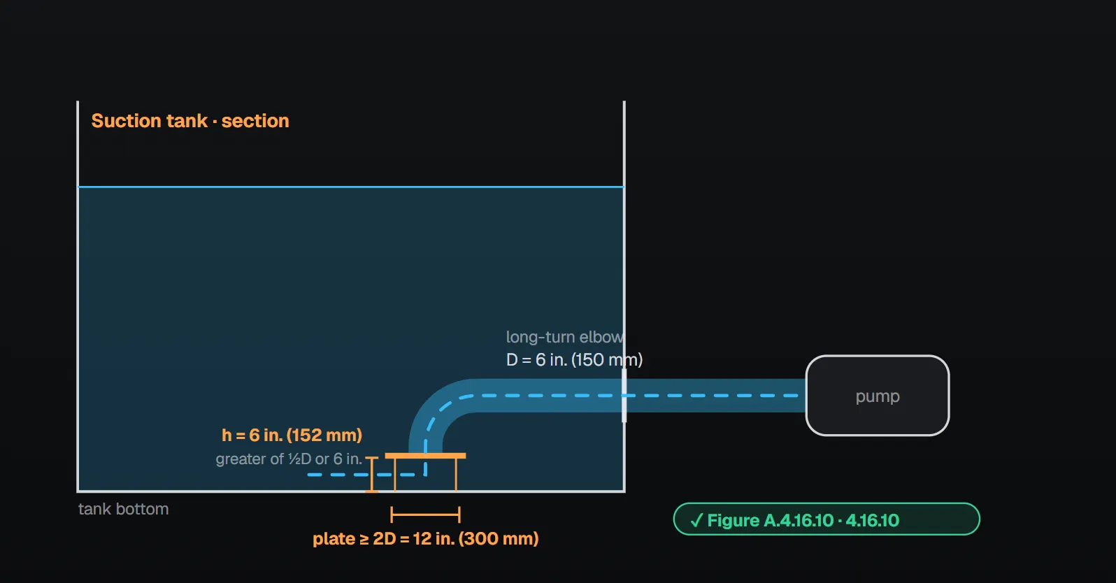
Where a tank is the suction source, the tank discharge outlet has an assembly that controls vortex flow in accordance with NFPA 22 (4.16.10). The sizing rule sits in NFPA 22; NFPA 20 gives an explanatory figure. Per Figure A.4.16.10 the plate is at least 2D × 2D (D: suction pipe diameter), its height above the tank bottom is the greater of ½D or 6 in. (152 mm), and the outlet turns down to the plate through a long-turn elbow. The legend of Figure A.6.3.1(a) likewise gives a square steel plate with sides at least twice the suction pipe diameter, at one-half the pipe diameter above the bottom with a minimum of 6 in. (152 mm).
The NFPA 20 Handbook (2022) commentary explains why: when water leaves at or near the bottom of a tank, a vortex forms as the level drops, and without a plate air enters the suction pipe; the bubbles create turbulence in the suction and damage the pump. The plate forces water down under it and up through a central hole of the suction pipe size into the elbow. The commentary recommends at least 48 in. (1219 mm) on each side, and the NFPA 22 (2018) extract in the Handbook treats a standard 48 in. × 48 in. (1219 mm × 1219 mm) plate as adequate for all normally used suction pipe sizes. It also suggests that where a pipe runs between the suction pit and the source, its source end turn vertically downward so debris does not settle into it, with an anti-vortex plate and a screen at that end.
Field watch points (from the sources)
- Single screen: the rule requires two (4.16.8.2); a single screen cannot be pulled once it clogs.
- Pulling a loaded screen: the Handbook (2022) warns that material can fall off and obstruct the second screen.
- Sizing on gross area: 1 in.²/gpm applies to the net opening at 150 percent flow below minimum water level; the overall area is 1.6 times that (4.16.8.4, 4.16.8.13).
- Ordinary material in mussel waters: only materials with demonstrated resistance are permitted (4.16.8.12).
- Tank outlet without a plate: the vortex carries air into the suction (Handbook commentary on 4.16.10); the rule requires the assembly (4.16.10).
Checklist
- Double screens at an open source, removable or cleanable in situ (4.16.8.2, 4.16.8.3).
- Net opening at least 1 in.²/gpm (170 mm² per L/min) at 150 percent of rated capacity, below minimum water level (4.16.8.4).
- Overall area 1.6 times the net opening, open area at least 62.5 percent (4.16.8.13, 4.16.8.11).
- Material and opening size: mesh 0.50 in. (12.7 mm), slot 0.125 in. (3.2 mm) maximum (4.16.8.6, 4.16.8.10).
- Screens removable without disturbing the suction pipe; a rake where they sit in a sump (4.16.8.5, 4.16.8.8).
- Periodic test pumping and screen cleaning scheduled (4.16.8.9).
- Tank outlet plate at least 2D × 2D, at the greater of ½D or 6 in. (152 mm) above the bottom (4.16.10, Figure A.4.16.10).
Frequently Asked Questions
When does a fire pump need suction screens?
Where water comes from an open source such as a pond or wet pit, the passage of materials that might clog the pump is obstructed and double intake screens are provided (NFPA 20-2025 4.16.8.1, 4.16.8.2).
How is the suction screen area calculated?
Below minimum water level the net opening is 1 in.² for each 1 gpm (170 mm² for each 1 L/min) at 150 percent of rated capacity (4.16.8.4); the overall area is 1.6 times that (4.16.8.13). The Handbook (2022) example gives a 1125 in.² net and 1800 in.² (12.5 ft²) overall area for a 750 gpm pump.
What material are suction screens made of?
Brass, copper, nickel-copper alloy, stainless steel or other equivalent corrosion-resistant metal; mesh no larger than 0.50 in. (12.7 mm), slots no larger than 0.125 in. (3.2 mm) (4.16.8.6, 4.16.8.10). Annex A.4.16.8 recommends brass or copper wire against aquatic fouling.
What size is the anti-vortex plate?
The rule refers to NFPA 22 (4.16.10). Per Figure A.4.16.10 the plate is at least 2D × 2D and sits at the greater of ½D or 6 in. (152 mm) above the tank bottom, fed by a long-turn elbow. The Handbook (2022) recommends at least 48 in. (1219 mm) on each side.
What happens without an anti-vortex plate?
Per the Handbook (2022) commentary, a vortex forms at the tank outlet as the level drops and air enters the suction pipe; the bubbles create turbulence and damage the pump. The standard requires the assembly (4.16.10).

SprinkCalc — Fire Sprinkler Design Across Three Standards
SprinkCalc covers hazard classification, design density and area, K-factor selection, water demand and hydraulic calculations for NFPA 13, FM Global and BS EN 12845 in a single iOS app, and exports a professional PDF report.
Download SprinkCalc on the App Store
MEP Calc — 110+ Engineering Calculators
MEP Calc bundles 110+ engineering modules in one iOS app: 21 fire calculations plus heating, cooling, HVAC, plumbing, steam and natural gas.
Download MEP Calc on the App StoreNFPA 20-2025, Standard for the Installation of Stationary Pumps for Fire Protection: 4.16.8.1–4.16.8.13, 4.16.9.2, 4.16.10; 7.3.4.1–7.3.4.3; Annex A.4.16.8, A.4.16.10, A.7.2.2.2, Figure A.4.16.10, Figure A.6.3.1(a), Figure A.7.2.2.2 (explanatory). NFPA 20 Handbook 2022 commentary: Section 4.16 (commentary on 4.16.8, 4.16.8.1, 4.16.8.12 and 4.16.10); Part III Section 4, NFPA 22 (2018) extract (anti-vortex plate).