A fire pump motor is chosen differently from an ordinary motor: it is of a given NEMA design, listed for fire pump service, and its locked rotor (starting) current is capped by tables in the standard. NFPA 20-2025 Section 9.5 sets out motor type, tables, service factor and marking.
In short: all motors comply with NEMA MG-1, are marked NEMA Design B (three-phase) or Design N or L (single-phase) and are specifically listed for fire pump service (9.5.1.1). Maximum locked rotor currents are in Tables 9.5.1.1(a), (b) and (c); for other voltages the Table 9.5.1.1(a) value is multiplied by 230 V divided by the motor voltage (9.5.1.5). Motors are rated for continuous duty (9.5.1.7). The maximum service factor is 1.15 and current in any phase never exceeds full-load current times service factor (9.5.2.1, 9.5.2.2). Above 3300 ft (1000 m) motors are operated or derated per Part 14 of NEMA MG-1 (9.5.2.5).
Motor type (9.5.1.1–9.5.1.4)
- All motors comply with NEMA MG-1, are marked as complying with NEMA Design B for three-phase or NEMA Design N or L for single-phase motors, and are specifically listed for fire pump service (9.5.1.1).
- Single-phase motors are used only in across-the-line starting applications (9.5.1.1.1).
- IEC motors, where used, are listed for fire service (9.5.1.1.2). NFPA 20 Handbook (2022): IEC motors are rated in kilowatts and typically have higher locked rotor currents than the corresponding NEMA Design B motors; coordination with the controller horsepower rating is considered in design.
- Direct-current, high-voltage (over 600 V), large-horsepower [over 500 hp (373 kW)], single-phase, universal-type and wound-rotor motors are outside 9.5.1.1 and may be used where approved (9.5.1.2).
- Part-winding motors have a 50-50 winding ratio so both windings carry equal current at nominal speed (9.5.1.3).
- Motors used with variable speed controllers meet Parts 30 or 31 of NEMA MG-1 and are listed, suitable and marked for inverter duty (9.5.1.4.1, 9.5.1.4.2); listing is not required if 9.5.1.2 applies (9.5.1.4.3). Reason: inverter duty motors have higher insulation voltage rating, suitable temperature rise rating and protection from bearing damage (A.9.5.1.4).
Locked rotor current tables
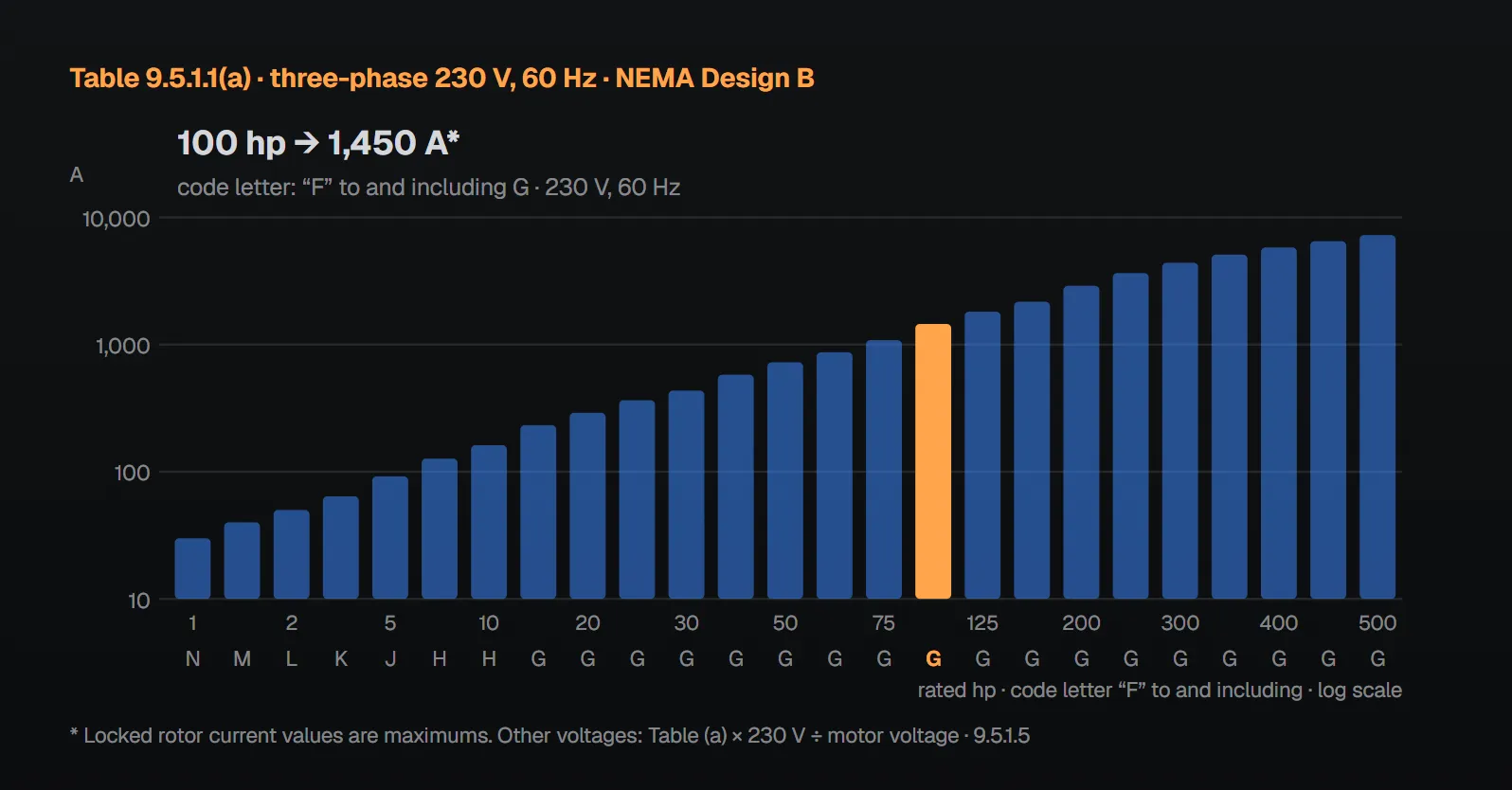
The tables give the maximum locked rotor current and the NFPA 70 locked rotor indicating code letter range for each rating. The asterisk note is the same in all three: locked rotor current values are maximums. Per the Handbook (2022), the values limit locked rotor current to roughly 5.0 to 6.6 times full-load current; fire pump controllers are designed, tested and listed for starting currents of 600 percent of full-load current, and motors drawing 700 or 800 percent result in unreliable and possibly unsafe installations. Because the emergency-run mechanical operator always starts the motor across the line, the limit matters even for reduced voltage and variable speed applications.
Table 9.5.1.1(a) Three-phase NEMA Design B motors
| Rated horsepower | Locked rotor current, three-phase 230 V at 60 Hz (A)* | Motor designation (NFPA 70 locked rotor indicating code letter) “F” to and including |
|---|---|---|
| 1 | 30 | N |
| 1½ | 40 | M |
| 2 | 50 | L |
| 3 | 64 | K |
| 5 | 92 | J |
| 7½ | 127 | H |
| 10 | 162 | H |
| 15 | 232 | G |
| 20 | 290 | G |
| 25 | 365 | G |
| 30 | 435 | G |
| 40 | 580 | G |
| 50 | 725 | G |
| 60 | 870 | G |
| 75 | 1085 | G |
| 100 | 1450 | G |
| 125 | 1815 | G |
| 150 | 2170 | G |
| 200 | 2900 | G |
| 250 | 3650 | G |
| 300 | 4400 | G |
| 350 | 5100 | G |
| 400 | 5800 | G |
| 450 | 6500 | G |
| 500 | 7250 | G |
* Locked rotor current values are maximums.
Table 9.5.1.1(b) Single-phase NEMA Design N and L motors
| Rated horsepower | Locked rotor current, single-phase 115 V at 60 Hz (A)* | Locked rotor current, single-phase 230 V at 60 Hz (A)* | ||
|---|---|---|---|---|
| Design N | Design L | Design N | Design L | |
| ⅙ | 20 | — | 12 | — |
| ¼ | 26 | — | 15 | — |
| ⅓ | 31 | — | 18 | — |
| ½ | 45 | 45 | 25 | 25 |
| ¾ | 61 | 61 | 35 | 35 |
| 1 | 80 | 80 | 45 | 45 |
| 1½ | — | — | 50 | |
| 2 | — | — | 65 | |
| 3 | — | — | 90 | |
| 5 | — | — | 135 | |
| 7½ | — | — | 200 | |
| 10 | — | — | 260 | |
* Locked rotor current values are maximums. In the 1½–10 hp rows the 115 V Design L cells are blank in the standard.
Table 9.5.1.1(c) Three-phase, 380 V, 50 Hz NEMA Design B motors
| Rated horsepower | Locked rotor current, three-phase 380 V at 50 Hz (A)* | Motor designation (NFPA 70 locked rotor indicating code letter) “F” to and including |
|---|---|---|
| 1 | 20 | P |
| 1½ | 27 | N |
| 2 | 34 | M |
| 3 | 43 | L |
| 5 | 61 | K |
| 7½ | 84 | J |
| 10 | 107 | H |
| 15 | 154 | H |
| 20 | 194 | H |
| 25 | 243 | H |
| 30 | 289 | H |
| 40 | 387 | H |
| 50 | 482 | H |
| 60 | 578 | H |
| 75 | 722 | H |
| 100 | 965 | H |
| 125 | 1207 | H |
| 150 | 1441 | H |
| 200 | 1927 | H |
| 250 | 2534 | H |
| 300 | 3026 | H |
| 350 | 3542 | H |
| 400 | 4046 | H |
| 450 | 4539 | H |
| 500 | 5069 | H |
* Locked rotor current values are maximums.
Other voltages and code letters (9.5.1.5, 9.5.1.6)
Locked rotor current for motors rated at other voltages is the Table 9.5.1.1(a) value multiplied by the ratio of 230 V to the motor voltage rating (9.5.1.5). For 230 V motors locked rotor current is approximately six times full-load current (A.9.5.1.5). Code letters for all other voltages conform with the 230 V letters of Table 9.5.1.1(a) (9.5.1.6). The Handbook (2022) gives a 100 hp example: 1603 A at 208 V, 834 A at 400 V, 804 A at 415 V, 580 A at 575 V. For 50 Hz, 380 V motors the standard has the separate Table 9.5.1.1(c).
Other motor rules
| Rule | Clause | Handbook (2022) reasoning |
|---|---|---|
| All motors rated for continuous duty | 9.5.1.7 | — |
| Motor-induced transients coordinated with 10.4.3.3 to prevent nuisance tripping of controller protective devices | 9.5.1.8 | At full voltage start, the first half-cycle peak can reach 12 times full-load current; reconnecting a still-spinning motor after a brief interruption, up to 18 times |
| Vertical shaft turbine pump motors are dripproof, squirrel-cage induction type with a nonreverse ratchet | 9.5.1.9.1, 9.5.1.9.2 | When power is cut, the weight of the water column can spin the pump backward, which can damage turbine pump bowls |
| Motor horsepower such that current in any phase, under any pump load and voltage unbalance, never exceeds full-load current times service factor | 9.5.2.1 | Maximum motor load may occur at or above 150 percent flow; the motor is never run into overload wherever it occurs on the curve |
| Maximum service factor 1.15; with a variable speed pressure limiting controller, as marked on the motor, never above 1.15 | 9.5.2.2 | Running into the service factor raises current by the same ratio: 1.15 gives 115 percent of full-load current |
| Service factors per NEMA MG-1; open dripproof, TEFC and TENV motors no larger than 1.15 | 9.5.2.3, 9.5.2.4 | — |
| Above 3300 ft (1000 m), operated or derated per Part 14 of NEMA MG-1 | 9.5.2.5 | At a 1.15 service factor winding heating rises about 32 percent (1.15 squared); thinner air reduces fan cooling |
| Terminal marking per Part 2 of NEMA MG-1; connecting diagram for multiple lead motors from the manufacturer | 9.5.3.1, 9.5.3.2 | Multiple lead motors are hard to wire correctly without a diagram |
| Motor marked with the maximum allowable service factor amperes; if also listed inverter duty, the maximum allowable service factor amperes on a VFD are marked too | 9.5.3.3, 9.5.3.3.1 | — |
Common field mistakes
- Unlisted or general purpose motor: 9.5.1.1 requires specific listing for fire pump service.
- Non-inverter-duty motor on a variable speed controller: contrary to 9.5.1.4.2.
- Locked rotor current above the table limit: the Handbook (2022) notes controllers are listed for 600 percent starting current.
- Counting on a service factor above 1.15: limited by 9.5.2.2 and 9.5.2.4.
- No nonreverse ratchet on a turbine pump motor: contrary to 9.5.1.9.2.
Checklist
- Motor marked NEMA Design B (or N/L) and listed for fire pump service; IEC motors listed for fire service (9.5.1.1, 9.5.1.1.2).
- Locked rotor current and code letter match Table 9.5.1.1(a)–(c) or the 9.5.1.5 ratio.
- Continuous duty; service factor ≤ 1.15 (9.5.1.7, 9.5.2.2).
- Inverter duty, marked motor on a variable speed controller (9.5.1.4).
- Derating considered above 3300 ft (1000 m) (9.5.2.5).
- Nameplate shows maximum allowable service factor amperes (9.5.3.3).
Frequently Asked Questions
What standard must a fire pump motor meet?
Per NFPA 20-2025 9.5.1.1, all motors comply with NEMA MG-1; three-phase motors are marked NEMA Design B, single-phase Design N or L, and all are specifically listed for fire pump service. IEC motors, where used, are listed for fire service (9.5.1.1.2).
What is the maximum locked rotor current of a 100 hp motor?
Per Table 9.5.1.1(a), 1450 A at 230 V, 60 Hz (code letter “F” to and including G); per Table 9.5.1.1(c), 965 A at 380 V, 50 Hz (“F” to and including H). For other voltages the Table (a) value is multiplied by 230 V divided by the motor voltage (9.5.1.5).
What service factor is allowed?
A maximum of 1.15 (9.5.2.2(1)); with a variable speed pressure limiting controller, as marked on the motor but never above 1.15 (9.5.2.2(2)). Current in any phase never exceeds full-load current times service factor (9.5.2.1).
Can a standard motor be used with a variable speed controller?
No. The motor meets Part 30 or 31 of NEMA MG-1 and is listed, suitable and marked for inverter duty (9.5.1.4.1, 9.5.1.4.2). Annex A.9.5.1.4 cites insulation, temperature rise and bearing protection.
Why is locked rotor current capped?
Per the NFPA 20 Handbook (2022), the tables limit locked rotor current to roughly 5.0 to 6.6 times full-load current, and controllers are listed for 600 percent starting current. The emergency-run mechanical operator always starts the motor at full voltage.

SprinkCalc — Fire Sprinkler Design Across Three Standards
SprinkCalc covers hazard classification, design density and area, K-factor selection, water demand and hydraulic calculations for NFPA 13, FM Global and BS EN 12845 in a single iOS app, and exports a professional PDF report.
Download SprinkCalc on the App Store
MEP Calc — 110+ Engineering Calculators
MEP Calc bundles 110+ engineering modules in one iOS app: 21 fire calculations plus heating, cooling, HVAC, plumbing, steam and natural gas.
Download MEP Calc on the App StoreNFPA 20-2025, Standard for the Installation of Stationary Pumps for Fire Protection: 9.5.1.1–9.5.3.3.1; Table 9.5.1.1(a), 9.5.1.1(b), 9.5.1.1(c); Annex A.9.5.1.4, A.9.5.1.5 (explanatory). NFPA 20 Handbook 2022 commentary: Section 9.5.