A fire pump is not just a pump: it is a unit made up of the pump, driver, controller and accessories (3.3.25). NFPA 20-2025 verifies the unit’s performance in two places: at the factory before shipment (4.5, 4.24) and in the field at the acceptance test (4.4.2, Section 14.2). This article covers unit responsibility, the certified shop test curve and the hydrostatic shop test, clause by clause.
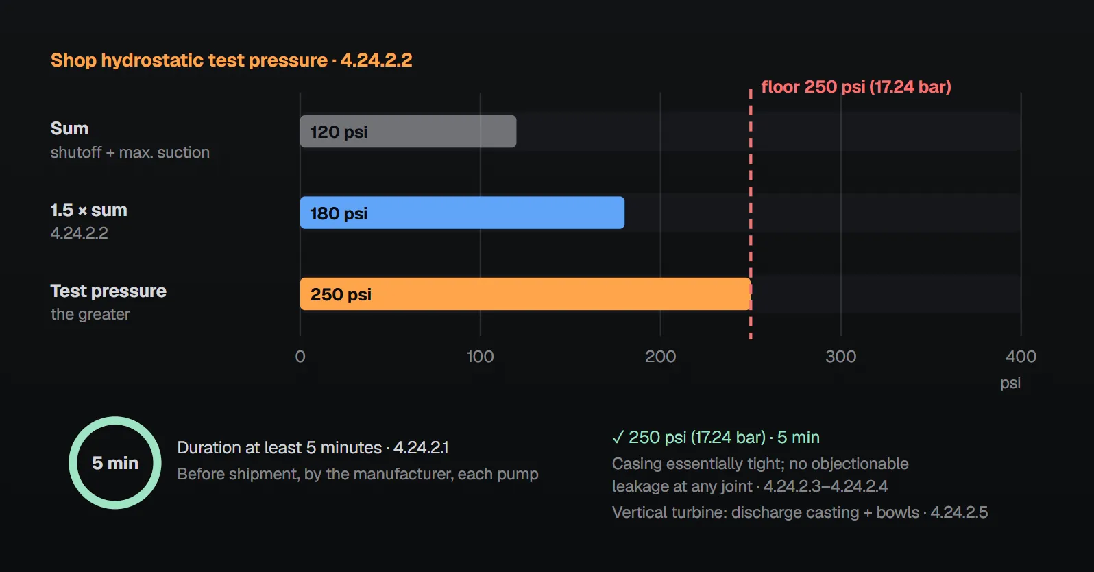
In short: when installed or when components are replaced, the pump, driver and controller perform as an entire unit in compliance with the standard (4.4.1), and the unit is field acceptance tested (4.4.2). A single entity is designated as responsible for acceptable unit performance of the pump, driver, controller and transfer switch equipment (4.4.3); this does not mean buying everything from one supplier (A.4.4.3). The manufacturer furnishes certified head–capacity and brake horsepower curves to the purchaser (4.5.1). Each pump is tested at the factory (4.24.1) and, before shipment, hydrostatically tested for at least 5 minutes at not less than 1.5 times the sum of shutoff head and maximum allowable suction head, and never below 250 psi (17.24 bar) (4.24.2.1, 4.24.2.2).
Performance as a unit
- The fire pump unit, consisting of pump, driver and controller, performs in compliance with this standard as an entire unit when installed or when components have been replaced (4.4.1).
- The complete unit is field acceptance tested in accordance with the standard (4.4.2; Section 14.2).
- A single entity is designated as responsible for acceptable unit performance of the pump, driver, controller and transfer switch equipment (4.4.3).
Annex A.4.4.3 defines unit responsibility as the accountability to answer and resolve any and all problems regarding installation, compatibility, performance and acceptance of the equipment, and says it should not be read as buying all components from a single supplier. The NFPA 20 Handbook (2022) answers the same question in an FAQ: single-source purchase is not required, but the listing and compatibility of all components should be considered. More on compatibility: fire pump, driver and controller compatibility.
According to the Handbook commentary on 4.4.3, the installer should be responsible for the unit until the equipment is accepted and formally turned over to the owner; on projects with a formal commissioning program, the responsibility may be given to a commissioning agent. When individual components are replaced, the contractor who installed them verifies that the entire unit functions as intended; component replacement testing after the initial acceptance is in NFPA 25. The 4.4.2 commentary describes the acceptance test as coordinated by the installing contractor, with the pump and controller manufacturers’ representatives, the owner, the design professional and the AHJ taking part.
Certified shop test curve
The manufacturer furnishes the purchaser with certified shop test curves showing the head capacity and brake horsepower of the pump (4.5.1). Some units need additional data:
| Pump or unit | Certified data required | Clause |
|---|---|---|
| Water mist positive displacement pumping unit | Flow, pressure and horsepower for each independent pump | 4.5.1.1 |
| Same unit, variable speed features deactivated | Flow, pressure and horsepower for the unit, with pumps activated in the controller’s operating sequence | 4.5.1.3, 4.5.1.3.1 |
| Water mist unit with variable speed features, activated | Flow, pressure and horsepower for the unit, same activation sequence | 4.5.1.4, 4.5.1.4.1 |
| Multistage multiport pump | Flow, pressure and horsepower for each outlet | 4.5.1.2 |
| Self-regulating variable speed unit | Two additional curves per pump showing flow, net pressure, power and speed: (1) at constant discharge pressure measured by the discharge transducer, (2) at constant boost pressure; from churn to beyond 150% of rated flow until maximum brake horsepower is reached | 4.5.1.5, A.4.5.1.5 |
Annex A.4.5.1.5 notes that the variable speed mode data show pressure, horsepower and speed on the Y axis and flow on the X axis. Multiport and self-regulating pumps have their own articles: multistage multiport fire pump, self-regulating variable speed fire pump.
What is the curve used for in the field?
A copy of the manufacturer’s certified pump test curve is available for comparison with the field acceptance test results (14.2.4.1); for multistage multiport pumps, the data for each discharge outlet (14.2.4.1.2). At all flow conditions tested, the installed pump equals the performance on the certified shop test curve within the accuracy limits of the test equipment (14.2.4.2). The pump performs at minimum, rated and peak loads without objectionable overheating of any component (14.2.6.3.1).
NFPA 20 Handbook (2022) commentary: the shop test verifies that the pump was tested by the manufacturer before shipment and performs properly under ideal conditions; the report should be submitted to the design professional and the AHJ for review. Acceptance test data are compared with this report to reveal performance differences. Speed variations can cause discrepancies between the curve and field results; minor differences can be corrected with the affinity laws referenced in Chapter 14. The curve is also used to identify the peak load, the highest point on the horsepower curve. Curve limits: fire pump curve: churn and 150%.
Shop tests and the hydrostatic test
Each individual pump is tested at the factory to provide detailed performance data and demonstrate compliance with specifications (4.24.1). The preshipment hydrostatic test follows these rules:
| Topic | Rule | Clause |
|---|---|---|
| Who, when | The manufacturer, each pump, before shipment from the factory | 4.24.2.1 |
| Duration | Not less than 5 minutes | 4.24.2.1 |
| Test pressure | Not less than 1.5 times the sum of the pump’s shutoff head and its maximum allowable suction head | 4.24.2.2 |
| Floor | In no case less than 250 psi (17.24 bar) | 4.24.2.2 |
| Acceptance | Casing essentially tight at test pressure; no objectionable leakage at any joint | 4.24.2.3, 4.24.2.4 |
| Vertical turbine pump | Both the discharge casting and the pump bowl assembly are tested | 4.24.2.5 |
The arithmetic of the rule: 1.5 times the sum exceeds 250 psi only when the sum is above 250 ÷ 1.5 ≈ 167 psi (11.5 bar); below that, 250 psi (17.24 bar) governs. The slider in the visual shows this comparison. Per the Handbook, shop test results are used for comparison with the field acceptance test; annual testing is covered by NFPA 25: fire pump performance test (NFPA 25).
Common field errors and the reason in the sources
| Error | Rule | Reason given in the sources |
|---|---|---|
| Buying components from different suppliers without designating a responsible entity | 4.4.3 | A.4.4.3: someone must answer installation, compatibility, performance and acceptance problems; not a single-supplier requirement |
| Not verifying the whole unit after a component replacement | 4.4.1 | Handbook: the contractor replacing it verifies the unit; NFPA 25 |
| No certified curve at the acceptance test | 14.2.4.1 | Handbook: comparison reveals performance differences |
| One curve for a multiport pump | 4.5.1.2, 14.2.4.1.2 | Handbook: each port has a different discharge pressure and is evaluated individually |
| Hydrostatic test below 250 psi or 1.5 times the sum, or shorter than 5 minutes | 4.24.2.1, 4.24.2.2 | The standard gives no reason |
Checklist
- Is a single entity designated for unit performance (4.4.3)?
- Have certified head–capacity and brake horsepower curves been received, with the extra data for special units (4.5.1–4.5.1.5)?
- Does the hydrostatic test record show duration (≥ 5 min) and pressure (≥ 1.5 × sum, ≥ 250 psi), including the bowl assembly for vertical turbines (4.24.2)?
- Is the certified curve on hand at acceptance, and do results match it within the accuracy limits (14.2.4.1, 14.2.4.2)?
- Was the whole unit verified after any component replacement (4.4.1)?
Frequently Asked Questions
Must the pump, driver and controller come from the same supplier?
No. Clause 4.4.3 only requires a single entity responsible for unit performance; Annex A.4.4.3 says this should not be construed as purchasing all components from one supplier. The NFPA 20 Handbook (2022) recommends considering the listing and compatibility of all components.
What does the certified shop test curve show?
The pump’s head–capacity and brake horsepower curves, furnished by the manufacturer to the purchaser (4.5.1). Extra data are required for water mist positive displacement units, multistage multiport pumps and self-regulating variable speed units (4.5.1.1–4.5.1.5).
How is the shop hydrostatic test pressure determined?
Take at least 1.5 times the sum of the shutoff head and the maximum allowable suction head; the result is never less than 250 psi (17.24 bar) (4.24.2.2). The test lasts at least 5 minutes (4.24.2.1); for vertical turbine pumps both the discharge casting and the bowl assembly are tested (4.24.2.5).
Must the installed pump match the certified curve?
Yes. At all flow conditions tested, the installed pump equals the certified shop curve performance within the accuracy limits of the test equipment (14.2.4.2). Handbook (2022): speed variations can cause discrepancies; minor differences can be corrected with the affinity laws.
What happens when a component is replaced?
The unit must still perform as an entire unit in compliance with the standard (4.4.1). Handbook (2022): the contractor who installed the replacement verifies that the whole unit functions as intended; replacement testing after the initial acceptance is in NFPA 25.

SprinkCalc — Fire Sprinkler Design Across Three Standards
SprinkCalc covers hazard classification, design density and area, K-factor selection, water demand and hydraulic calculations for NFPA 13, FM Global and BS EN 12845 in a single iOS app, and exports a professional PDF report.
Download SprinkCalc on the App Store
MEP Calc — 110+ Engineering Calculators
MEP Calc bundles 110+ engineering modules in one iOS app: 21 fire calculations plus heating, cooling, HVAC, plumbing, steam and natural gas.
Download MEP Calc on the App StoreNFPA 20-2025, Standard for the Installation of Stationary Pumps for Fire Protection: 3.3.25; 4.4.1–4.4.3; 4.5.1, 4.5.1.1–4.5.1.5, 4.5.1.3.1, 4.5.1.4.1; 4.24.1, 4.24.2.1–4.24.2.5; 14.2.4.1, 14.2.4.1.2, 14.2.4.2, 14.2.6.3.1; Annex A.4.4.3, A.4.5.1.5 (explanatory). NFPA 20 Handbook 2022 commentary: 4.4.1 FAQ, 4.4.2 and 4.4.3 commentary; 4.5.1 and 4.5.1.2 commentary; 4.24 commentary.