NFPA 20-2025 accepts electric motors, diesel engines, steam turbines or a combination of them as fire pump drivers (4.7.2). The steam-specific rules sit in two places: steam power supply dependability (4.23) and Chapter 13, Steam Turbine Drive. Per the NFPA 20 Handbook (2022) commentary, existing steam-driven installations are rare and new ones very rare; the standard still recognizes a steam turbine with a reliable steam source as an acceptable driver.
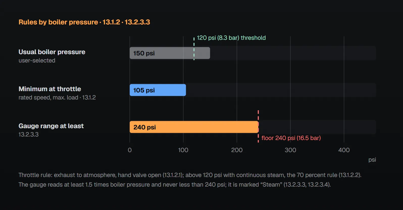
In short: the dependability of the steam supply and the steam supply system is carefully considered in each case, including the effect of interrupted transmission piping (4.23.1.1, 4.23.1.2). With boiler pressure not exceeding 120 psi (8.3 bar), the turbine drives the pump at rated speed and maximum load with as little as 80 psi (5.5 bar) at the throttle; at higher boiler pressure with steam continuously maintained, 70 percent of the usual boiler pressure replaces the 80 psi (13.1.2.1, 13.1.2.2). A speed governor holds rated speed, and an independent emergency governor shuts off steam at approximately 20 percent above rated speed (13.2.2.1, 13.2.2.5). The steam gauge reads at least 1.5 times boiler pressure and never less than 240 psi (16.5 bar) (13.2.3.3).
Steam supply dependability (4.23, Annex A.13.3)
Careful consideration is given in each case to the dependability of the steam supply and the steam supply system (4.23.1.1), including the possible effect of interrupted transmission piping on the property or in adjoining buildings that could threaten the property (4.23.1.2). Annex A.13.3 adds:
- The fire pump steam supply should preferably be an independent line from the boilers, run so that a fire anywhere on the property will not damage it.
- Other steam lines from the boilers should be controlled by valves in the boiler room, so they can be shut off in an emergency and all steam left for the fire pump. Strainers in steam lines to turbines are recommended.
Per the Handbook (2022) commentary, a steam turbine-driven pump is in most cases a secondary supply rather than the primary automatic pump; if the steam supply shuts down, so does the turbine, so an alternate steam source or a pump with a different power source (diesel) should be provided as backup.
Turbine acceptability and capacity (13.1)
- Steam turbines of adequate power are acceptable prime movers for fire pumps; their reliability has been proved in commercial work (13.1.1.1, 13.1.1.1.1).
- The turbine is directly connected to the fire pump (13.1.1.2). Handbook (2022): direct connection includes a flexible coupling for alignment; no gear is intended, and pump and driver run at the same rpm.
- When ordering, the purchaser specifies the rated and maximum pump loads at rated speed, the rated speed, the boiler pressure, the steam pressure at the throttle (if possible) and the steam superheat (13.1.2.3).
| Boiler pressure | Minimum throttle pressure at which the turbine drives the pump at rated speed and maximum load | Clause |
|---|---|---|
| Not exceeding 120 psi (8.3 bar) | 80 psi (5.5 bar), exhausting to atmosphere with the hand valve open | 13.1.2.1 |
| Exceeding 120 psi (8.3 bar), steam continuously maintained | 70 percent of the usual boiler pressure instead of 80 psi | 13.1.2.2 |
Per the Handbook (2022) commentary, the difference between the maximum and minimum pressures in 13.1.2.1 represents steam friction loss in the piping while the turbine runs. Turbine selection gives prime consideration to total steam consumption commensurate with the available supply (13.1.3.1); Annex A.13.1.3 recommends single-stage turbines of maximum reliability and simplicity where the supply permits. Multistage turbines are designed to bring the pump up to speed without a warmup time (13.1.3.2). The Handbook adds that a reserve of steam for operation at 150 percent of pump capacity should be anticipated, that the turbine should be kept warm, and that full steam pressure should not be injected into cold equipment.
Casing and steam connections (13.2.1)
- The casing permits access with the least possible removal of parts or piping (13.2.1.1); per Annex A.13.2.1.1 it can be cast iron.
- A safety valve connected directly to the turbine casing relieves high steam pressure in the casing (13.2.1.2).
- The main throttle valve is in a horizontal run of pipe connected directly to the turbine, with a water leg on the supply side connected to a suitable steam trap that drains all condensate from the supply line (13.2.1.3.1 through 13.2.1.3.3).
- Steam and exhaust chambers have condensate drains, discharging through adequate traps when the turbine is automatically controlled (13.2.1.3.4, 13.2.1.3.5). If the exhaust pipe discharges vertically, an open, unvalved drain at the bottom elbow discharges to a safe location (13.2.1.3.6, 13.2.1.3.7).
- The nozzle chamber, governor-valve body, pressure regulator and other steam-carrying parts are made of a metal able to withstand the maximum temperatures (13.2.1.4).
Governor, gauge, rotor and shaft (13.2.2 through 13.2.6)
| Rule | Value | Clause |
|---|---|---|
| Speed governor | Maintains rated speed at maximum pump load | 13.2.2.1 |
| Regulation range | Rated speed within a total range of approximately 8 percent from no load to full load, with normal steam pressure and hand valve closed, or with steam down to 80 psi (5.5 bar) [or to 70 percent of full pressure above 120 psi] and hand valve open | 13.2.2.2 |
| Speed adjustment | Approximately 5 percent above and 5 percent below rated speed at rated load | 13.2.2.3 |
| Emergency governor | Independent; shuts off steam at approximately 20 percent above rated pump speed | 13.2.2.4, 13.2.2.5 |
| Steam gauge | Listed, on the entrance side of the governor; 0.25 in. (6 mm) tap on the nozzle chamber; at least 1.5 times boiler pressure and never less than 240 psi (16.5 bar); marked “Steam” | 13.2.3.1 through 13.2.3.4 |
| Rotor | Suitable material; the first unit of a rotor design is type tested in the shop at 40 percent above rated speed, later units of the same design at 25 percent above | 13.2.4.1 through 13.2.4.3 |
| Shaft | High-grade steel; flexible coupling where pump and turbine are independent units; one-piece shaft with only two bearings for an overhung rotor; critical speed high enough to run up to 120 percent of rated speed without objectionable vibration | 13.2.5.1 through 13.2.5.4 |
| Bearings | Split-type shells and caps for sleeve bearings; ball bearings acceptable after a satisfactory commercial record; visible oil level indication | 13.2.6.1 through 13.2.6.2.2 |
Per the Handbook (2022) commentary, no steam turbine drivers are currently listed; approval of the individual driver is made on sound engineering principles and presented to the authority having jurisdiction.
Installation and automatic operation (13.3, Annex A)
Steam supply, exhaust and boiler feed details are carefully planned for reliable and effective operation of a steam turbine-driven fire pump (13.3). Annex A.13.3 and A.13.2.1.1 recommend:
- The steam throttle at the pump closes against steam pressure, preferably a globe pattern with a solid disc; gate valves are undesirable because they cannot readily be made leaktight.
- In general, no pressure-reducing valve in the steam pipe to the fire pump, because a deranged valve can obstruct the line. In most cases the turbine is protected by sizing the 13.2.1.2 safety valve so casing pressure stays at or below 25 psi (1.7 bar), piped outside the pump room and, if possible, to where the pump attendant can see the discharge.
- The exhaust pipe runs directly to atmosphere, contains no valves of any type and is not connected to any condenser, heater or other exhaust system.
- If the usual boiler feed fails, an emergency boiler feed of about 2 in. (50 mm) can be taken from the pump discharge, with a controlling valve at the pump and a check valve, preferably in the boiler room; not where a potable supply could be contaminated.
- Where the pump must start automatically and keep running on a pressure signal, a pilot-type pressure control valve in the bypass around the manual control valve is recommended; a direct-acting pressure regulator on the turbine control valve is not (A.13.2.1.1).
Steam turbine at the acceptance test (14.2.6.9, 14.2.9)
At the field acceptance test the steam turbine maintains its speed within the limits of 13.2.2 (14.2.6.9). The emergency governor valve is operated to demonstrate satisfactory performance; hand tripping is acceptable (14.2.9.1, 14.2.9.2). Per Annex A.14.2.6, the turbine should always be kept warmed up for instant full-speed operation, and automatic starting should not depend on any manual valve operation or low-speed period; if the casing safety valve blows, steam is shut off and the exhaust piping is checked for a closed valve or obstruction. For the whole test see fire pump field acceptance test.
Common field mistakes
- Selecting a turbine without checking the available steam: 13.1.3.1 requires steam consumption commensurate with the supply.
- A valve in the exhaust pipe: per Annex A.13.3 the exhaust pipe contains no valves of any type.
- Valving the drain at the bottom elbow of a vertical exhaust: contrary to 13.2.1.3.7.
- Not operating the emergency governor at acceptance: 14.2.9.1 requires it.
Checklist
- Steam supply dependability and transmission piping interruption assessed (4.23.1.1, 4.23.1.2).
- Turbine capacity: 80 psi or 70 percent rule; ordering data specified (13.1.2.1 through 13.1.2.3).
- Steam consumption matches supply; no warmup time for multistage turbines (13.1.3.1, 13.1.3.2).
- Safety valve on the casing; throttle valve in a horizontal run with water leg and trap; drains (13.2.1.2 through 13.2.1.3.7).
- Governor, ±5 percent adjustment, emergency governor at 20 percent (13.2.2.1 through 13.2.2.5).
- Listed “Steam” gauge, 6 mm tap, at least 1.5 times and 240 psi (13.2.3.1 through 13.2.3.4).
- At acceptance, speed within 13.2.2 and emergency governor operated (14.2.6.9, 14.2.9).
Frequently Asked Questions
Does NFPA 20 accept a steam turbine as a fire pump driver?
Yes. Acceptable drivers are electric motors, diesel engines, steam turbines or a combination (4.7.2); steam turbines of adequate power whose reliability has been proved in commercial work are acceptable prime movers (13.1.1.1, 13.1.1.1.1). Steam supply dependability is considered in each case (4.23.1.1).
At what steam pressure must the turbine drive the pump?
With boiler pressure not exceeding 120 psi (8.3 bar), at as little as 80 psi (5.5 bar) at the throttle, at rated speed and maximum pump load (13.1.2.1). At higher boiler pressure with steam continuously maintained, 70 percent of the usual boiler pressure replaces the 80 psi (13.1.2.2).
When does the emergency governor act?
The independent emergency governing device shuts off steam at approximately 20 percent above rated pump speed (13.2.2.4, 13.2.2.5). At acceptance the emergency governor valve is operated; hand tripping is acceptable (14.2.9.1, 14.2.9.2).
What range must the steam gauge have?
The listed steam gauge is on the entrance side of the speed governor, reads at least 1.5 times boiler pressure and never less than 240 psi (16.5 bar), and is marked “Steam” (13.2.3.1, 13.2.3.3, 13.2.3.4). A 0.25 in. (6 mm) gauge tap is on the nozzle chamber (13.2.3.2).
Can a pressure-reducing valve be used in the steam line?
Annex A.13.3 generally advises against it: a deranged valve can obstruct the line, and in most cases the turbine is protected by a safety valve limiting casing pressure to 25 psi (1.7 bar). If one is used, it should have no stuffing box or piston, a globe-valve bypass, and be smaller than the turbine steam pipe.

SprinkCalc — Fire Sprinkler Design Across Three Standards
SprinkCalc covers hazard classification, design density and area, K-factor selection, water demand and hydraulic calculations for NFPA 13, FM Global and BS EN 12845 in a single iOS app, and exports a professional PDF report.
Download SprinkCalc on the App Store
MEP Calc — 110+ Engineering Calculators
MEP Calc bundles 110+ engineering modules in one iOS app: 21 fire calculations plus heating, cooling, HVAC, plumbing, steam and natural gas.
Download MEP Calc on the App StoreNFPA 20-2025, Standard for the Installation of Stationary Pumps for Fire Protection: 4.7.2; 4.23.1.1, 4.23.1.2; 13.1.1.1–13.1.3.2; 13.2.1.1–13.2.6.2.2; 13.3; 14.2.6.9; 14.2.9.1, 14.2.9.2; Annex A.13.1.3, A.13.2.1.1, A.13.3, A.14.2.6 (explanatory). NFPA 20 Handbook 2022 commentary: 4.23, Sections 13.1 through 13.3.