NFPA 11 does not write foam system hydraulics from scratch. It leaves water and solution pipe calculations to NFPA 13 and the water supply system to NFPA 24. It does, however, set the points that are specific to foam: the variation allowed in distribution, which formula and fluid properties apply to concentrate piping, which C value to use, and the pressure and flow limits that pumps and proportioners must meet. This article collects those rules in one place and gives an example using only NFPA 11 values.
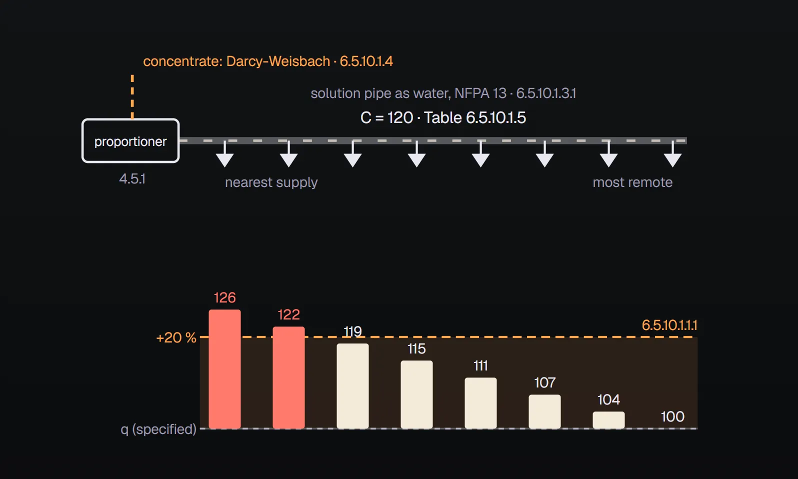
In short: In a foam-water deluge system, pipe sizes are adjusted for a maximum variation of 20 percent above the specified discharge per sprinkler or nozzle (6.5.10.1.1.1). Solution piping is sized as if carrying plain water, with calculations to NFPA 13 (6.5.10.1.3, 6.5.10.1.3.1). Concentrate piping uses Darcy-Weisbach, with friction factors from Figures 6.5.10.1.4.1(a)–(d) and a Reynolds number based on the actual density and the viscosity at the lowest storage temperature (6.5.10.1.4–6.5.10.1.4.3). For alcohol-resistant concentrates, friction data come from the manufacturer (6.5.10.1.4.4). C values are in Table 6.5.10.1.5.
Where are the hydraulics for tank and dike systems?
Chapter 5 of NFPA 11-2024 (tank, fueling and spill area systems) ends with 5.9 supplementary protection; it has no hydraulic calculation section of its own. For these systems the hydraulic rules sit in the Chapter 4 component clauses and in a few limits inside the tank sections:
- Basis of design: the tank needing the largest foam solution flow, including supplementary hose streams (5.2.2).
- Water quantity: enough for all devices that may operate at once for the specified time, including water for other firefighting operations (4.2.1.2, 4.2.1.2.1).
- Inlet pressure: at the foam system inlet (foam generator, air foam maker and so on) under the required flow, at least the minimum pressure the system was designed for (4.2.1.3). The water supply system is designed to NFPA 24 (4.2.1.5).
- Fire department connection: carries a placard giving the minimum pressure needed for the foam system's hydraulic design (4.2.3.6).
- Concentrate piping: Darcy-Weisbach for Newtonian concentrates, manufacturers' friction loss data for alcohol-resistant (non-Newtonian) ones (4.7.1.7).
- Solution piping: Hazen-Williams C of 120 for galvanized steel; other corrosion-resistant materials per NFPA 13 (4.7.2.9).
- Subsurface back pressure: pipe sizes and lengths beyond the foam maker and the maximum fuel depth must keep back pressure within the device's tested and listed range (5.2.6.4).
Proportioner and concentrate pump
- The proportioning system meets its listed minimum flow based on the minimum and maximum system discharge (4.5.1).
- Concentrate pump rated capacity is at or above the maximum system demand (4.6.2.1).
- To ensure positive injection, the pump discharge pressure at design capacity exceeds the maximum water pressure available under any condition at the injection point (4.6.2.2).
- In in-line balanced-pressure proportioning, a pressure regulating device in the pump return line holds the concentrate supply line at a constant pressure above the maximum water pressure at all design flows (4.5.2.2(3)).
- Pumps able to overpressurise the system have relief from discharge to supply, and overpressure stays within the concentrate piping's working pressure (4.6.3.1, 4.6.3.2).
Foam-water deluge systems (6.5.10.1)
For the foam-water sprinkler and spray systems of Chapter 6, hydraulic design has two aims: uniform foam and water distribution, and allowance for head loss in the supply piping (6.5.10.1.1).
The 20 percent rule
Pipe sizes are adjusted on the basis of a maximum variation of 20 percent above the specified discharge rate per sprinkler or nozzle (6.5.10.1.1.1). The rule limits upward variation only. Sizes are set by detailed friction loss calculations, which must show the relationship between water supply and water demand (6.5.10.1.2, 6.5.10.1.2.1).
Solution piping: as water, to NFPA 13
Hydraulic calculations for piping carrying water or foam solution follow NFPA 13 (6.5.10.1.3), and solution piping is sized as if it carried plain water (6.5.10.1.3.1). NFPA 11 does not repeat the method or formula; those are in NFPA 13. Hazen-Williams C values for friction loss come from Table 6.5.10.1.5 (6.5.10.1.5).
Concentrate piping: Darcy-Weisbach
For piping carrying foam concentrate NFPA 11 requires the Darcy-Weisbach formula rather than Hazen-Williams (6.5.10.1.4), and sets three rules for its inputs:
- Friction factors are selected from the graphs in Figures 6.5.10.1.4.1(a) to (d) (6.5.10.1.4.1).
- The Reynolds number uses the actual density (or specific gravity) of the concentrate to be used (6.5.10.1.4.2).
- The viscosity is the actual viscosity of the concentrate at the lowest anticipated storage temperature (6.5.10.1.4.3).
For piping with alcohol-resistant concentrate the designer consults the concentrate manufacturer for friction characteristics (6.5.10.1.4.4). NFPA 11 gives no figures here.
| Figure | Pipe | Reynolds range | Curves |
|---|---|---|---|
| 6.5.10.1.4.1(a) | Cast iron | R ≤ 105 | 3, 4, 6, 8 in.; laminar, critical, transition and complete turbulence zones |
| 6.5.10.1.4.1(b) | Cast iron | R ≥ 105 | 3, 4, 6, 8 in. |
| 6.5.10.1.4.1(c) | Steel | R ≤ 105 | ⅛ to 10 in.; laminar, critical, transition and complete turbulence zones |
| 6.5.10.1.4.1(d) | Steel | R ≥ 105 | ⅛ to 10 in. |
Diagrams (a) and (c) show the laminar-flow line f = 64/R.
Foam-water wet, dry and preaction systems (6.5.10.2)
- The aims are again uniform distribution and allowance for head loss in system piping (6.5.10.2.1).
- Two sets of calculations are provided: one for the most hydraulically demanding condition and one for the least demanding design area, each balanced to the available water supply (6.5.10.2.2).
- That balance confirms that actual discharge will not exceed the ability of the concentrate supply to provide foam solution as specified in 6.5.2.3.1 and 6.5.2.3.2 (6.5.10.2.3).
- Pipe sizes follow detailed friction loss calculations showing supply against demand (6.5.10.2.4, 6.5.10.2.4.1).
- Calculations follow NFPA 13, solution piping is treated as water, and C values come from Table 6.5.10.1.5 (6.5.10.2.5, 6.5.10.2.5.1, 6.5.10.2.6).
- Concentrate piping follows 6.5.10.1.4, with manufacturer data for alcohol-resistant concentrates (6.5.10.3.1, 6.5.10.3.2).
Table 6.5.10.1.5: Hazen-Williams C values
| Pipe or tube | C value |
|---|---|
| Unlined cast or ductile iron | 100 |
| Black steel (dry systems including preaction) | 100 |
| Black steel (wet systems including deluge) | 120 |
| Black steel (dry systems including preaction) using nitrogen | 120 |
| Galvanized steel (dry systems including preaction) | 100 |
| Galvanized steel (wet systems including deluge) | 120 |
| Galvanized steel (dry systems including preaction) using nitrogen | 120 |
| Plastic (listed), all | 150 |
| Cement-lined cast or ductile iron | 140 |
| Copper tube, brass or stainless steel | 150 |
| Asbestos cement | 140 |
| Concrete | 140 |
The table notes allow the authority having jurisdiction to accept other C values, and require any nitrogen supply to be installed to NFPA 13. The table is extracted from NFPA 13.
Worked example: the 20 percent band
A foam-water deluge system has 12 nozzles, each with a specified discharge of 100 L/min, and uses a 3 % concentrate. The 100 L/min is our example value, not an NFPA 11 figure. We assume the most remote nozzle delivers exactly the specified flow.
| Step | Working | Result | Clause |
|---|---|---|---|
| Highest flow per nozzle | 100 × 1.20 | 120 L/min | 6.5.10.1.1.1 |
| Total solution flow range | 12 × 100 … 12 × 120 | 1,200 – 1,440 L/min | 6.5.10.1.1.1 |
| Concentrate flow (3 %) | 1,200 × 0.03 … 1,440 × 0.03 | 36 – 43.2 L/min | 3.3.1, 4.3.2.5.1 |
| Proportioner | Listed minimum flow met for the minimum and maximum system flow | Check against listing | 4.5.1 |
| Concentrate pump | Capacity at or above maximum demand; discharge pressure above maximum water pressure | ≥ 43.2 L/min | 4.6.2.1, 4.6.2.2 |
| Solution pipe C | Galvanized steel, deluge (wet) | 120 | Table 6.5.10.1.5 |
| Concentrate pipe | Darcy-Weisbach; actual density, viscosity at lowest storage temperature | From concentrate data | 6.5.10.1.4.1–6.5.10.1.4.3 |
If the calculation gives 130 L/min at the nozzle nearest the supply, the variation is 30 percent and the 20 percent limit is broken. Pipe sizes are increased and the friction loss calculation repeated (6.5.10.1.2). Had the system been dry-pipe galvanized steel, C would fall to 100, or be taken as 120 with nitrogen. To work with density and area criteria, use the foam-water sprinkler calculator, and for tank systems the NFPA 11 design criteria calculator. Concentrate supply and proportioning methods are covered in foam concentrate supply and proportioning.
Common mistakes
- Calculating concentrate piping with Hazen-Williams as if it were water (6.5.10.1.4).
- Taking viscosity at a mild temperature instead of the lowest storage temperature (6.5.10.1.4.3).
- Assuming friction for alcohol-resistant concentrate without manufacturer data (6.5.10.1.4.4).
- Using the wet-system C value in a dry or preaction system (Table 6.5.10.1.5).
- Calculating only the most demanding area in a wet, dry or preaction system and skipping the second set (6.5.10.2.2).
- Choosing concentrate pump discharge pressure against average rather than maximum water pressure (4.6.2.2).
Frequently Asked Questions
What does the NFPA 11 20 percent rule mean?
In a foam-water deluge system, pipe sizes are adjusted so that discharge at any sprinkler or nozzle varies by no more than 20 percent above the specified rate (6.5.10.1.1.1). With a specified 100 L/min, no nozzle should exceed 120 L/min.
How is foam solution piping calculated?
Solution piping is sized as if it carried plain water and calculated to NFPA 13 (6.5.10.1.3, 6.5.10.1.3.1). Hazen-Williams C values come from NFPA 11 Table 6.5.10.1.5.
Which formula applies to foam concentrate piping?
The Darcy-Weisbach formula (6.5.10.1.4). Friction factors come from Figures 6.5.10.1.4.1(a)–(d), and the Reynolds number uses the concentrate's actual density and its actual viscosity at the lowest anticipated storage temperature (6.5.10.1.4.1–6.5.10.1.4.3).
What C value applies to a dry-pipe foam-water system?
Table 6.5.10.1.5 gives C = 100 for black and galvanized steel in dry systems including preaction, or C = 120 where the system uses nitrogen. The authority having jurisdiction may allow other values.
How is friction loss found for alcohol-resistant concentrate?
NFPA 11 gives no figures. The designer obtains friction characteristics from the concentrate manufacturer (6.5.10.1.4.4, 6.5.10.3.2), and Chapter 4 likewise points to manufacturers' friction loss data for these concentrates (4.7.1.7).

SprinkCalc — Fire Sprinkler Design Across Three Standards
SprinkCalc covers hazard classification, design density and area, K-factor selection, water demand and hydraulic calculations for NFPA 13, FM Global and BS EN 12845 in a single iOS app, and exports a professional PDF report.
Download SprinkCalc on the App Store
MEP Calc — 110+ Engineering Calculators
MEP Calc bundles 110+ engineering modules in one iOS app: 21 fire calculations plus heating, cooling, HVAC, plumbing, steam and natural gas.
Download MEP Calc on the App StoreNFPA 11, Standard for Low-, Medium-, and High-Expansion Foam, 2024 edition: 3.3.1 (p. 11-10); 4.2.1.2–4.2.1.5, 4.2.3.6 (p. 11-13); 4.3.2.5.1, 4.5.1, 4.5.2.2, 4.6.2, 4.6.3 (p. 11-15); 4.7.1.7, 4.7.2.9 (p. 11-16); 5.2.2 (p. 11-18); 5.2.6.4 (pp. 11-20, 11-21); end of Chapter 5 at 5.9 (p. 11-29); 6.5.10.1 and Figure 6.5.10.1.4.1(a) (p. 11-34); Figures 6.5.10.1.4.1(b), (c), 6.5.10.2, 6.5.10.3 (p. 11-35); Figure 6.5.10.1.4.1(d) and Table 6.5.10.1.5 (p. 11-36). Values were read from images of the standard's PDF pages. For formulae and calculation steps see NFPA 13, to which NFPA 11 refers. The binding text is the standard itself and the decision of the authority having jurisdiction.