NFPA 11 lists seven ways of introducing foam concentrate into water (4.5). They all do the same job, but each draws its energy from a different place, behaves differently at low flow and carries different limits. This article sets the methods side by side: what pushes or pulls the concentrate, where the standard allows each one, what happens to the percentage when the flow drops, and what is checked at acceptance.
The clause-by-clause rules for the four balanced-pressure injection arrangements are in concentrate supply and proportioning, and the P&ID and site installation in foam system installation; they are not repeated here. Annex A material is explanatory, not mandatory, and is cited as "Annex".
What proportioning has to achieve
Proportioning is the continuous introduction of concentrate into the water stream at the recommended ratio (3.3.26). Two yardsticks apply to every method. The first is flow range: the proportioning system must meet the listed minimum flow rate based on the system's minimum and maximum discharge (4.5.1). The second is the acceptance tolerance: the induction rate, as a percentage of solution flow, must lie within minus 0 to plus 30 percent of the manufacturer's listed concentration, or plus 1 percentage point, whichever is less (12.6.5). Our own arithmetic gives bands of 1.0–1.3 % for a 1 percent concentrate, 3.0–3.9 % for 3 percent and 6.0–7.0 % for 6 percent.
The seven methods in one table (4.5)
| Method | What moves the concentrate? | Limits and notes in Annex A | Clause |
|---|---|---|---|
| 1. Self-educting nozzle | A venturi in the nozzle draws concentrate through a short pipe or hose (3.3.24.2) | Container bottom no more than 1.8 m (6 ft) below the foam maker; hose length and size to the manufacturer (Annex A.3.3.4) | 4.5(1) |
| 2. In-line eductor | Sub-atmospheric pressure created by water flow at the venturi throat (3.3.4, 3.3.4.1) | Designed for the flow of its foam maker; very sensitive to downstream pressure; pressure drop about one third of inlet pressure; container bottom no more than 1.8 m below (Annex A.3.3.4.1); open-head or deluge systems only (Annex A.4.5.2.3(3)) | 4.5(2), 4.5.2.3(3) |
| 3a. Pressure proportioning tank, no bladder | Water entering the tank displaces concentrate of specific gravity at least 1.15 through an orifice (3.3.32.2) | Concentrates with a specific gravity close to water cause problems; capacity about 50–200 % of rating; pressure drop 34–207 kPa (5–30 psi); no top-up during operation, so the system is stopped, drained and refilled; percentage drops markedly at low flow (Annex A.3.3.32.2) | 4.5(3) |
| 3b. Pressure proportioning tank, bladder | Water squeezes the bladder; concentrate goes to a modified venturi (3.3.32.1) | Same limits as the plain tank, but usable with all concentrate types (Annex A.3.3.32.2) | 4.5(3), 4.5.2.2(2) |
| 4. Around-the-pump proportioner | An eductor in a bypass from pump discharge to suction draws concentrate into the suction (3.3.28) | Pump suction pressure must be essentially zero or on the vacuum side; container bottom no more than 1.8 m below; the bypass uses 38–151 L/min (10–40 gpm) of water, which comes off the pump's net delivery (Annex A.3.3.28) | 4.5(4), 4.5.2.3(2) |
| 5. Direct injection, variable output pump | A variable output concentrate pump controlled from concentrate and water flowmeters (3.3.26.3) | Unaffected by water pressure; not interrupted while the concentrate tank is refilled (Annex A.3.3.26.3) | 4.5(5) |
| 6. Coupled water-motor driven pump | A positive displacement water motor in the supply drives a positive displacement concentrate pump (3.3.26.2) | The ratio of volumes per revolution sets the percentage; changes in pressure, flow or viscosity do not alter it (Annex A.3.3.26.2); a positive displacement water motor system needs no external power (Annex A.3.3.26.3) | 4.5(6) |
| 7. Balanced pressure, pump type | A concentrate pump and valve balance foam and water pressures at a modified venturi; the metering orifice sits in the foam inlet (3.3.26.1) | Correct when both hands of the duplex gauge match, done automatically by a differential pressure diaphragm valve; capacity about 50–200 %, pressure drop 34–207 kPa, separate pump needed (Annex A.3.3.26.1) | 4.5(7), 4.5.2.2(1) |
Without a row of its own in the list, 4.5.2.2(3) defines one more variant: in-line balanced pressure. A concentrate pump or bladder tank works with a listed pressure reducing valve; concentrate pressure stays constant and above the highest water pressure at the proportioner inlet at every design flow, and a balancing valve built into the proportioner trims it to the incoming water pressure (3.3.26.1.1). A bladder tank with a water pressure reducing valve upstream of the proportioner can replace the pump package (Annex A.3.3.26.1.1). Annex A.12.9.4(4) notes that such positive-pressure systems usually hold concentrate 1–2 bar (15–30 psi) above the water supply.
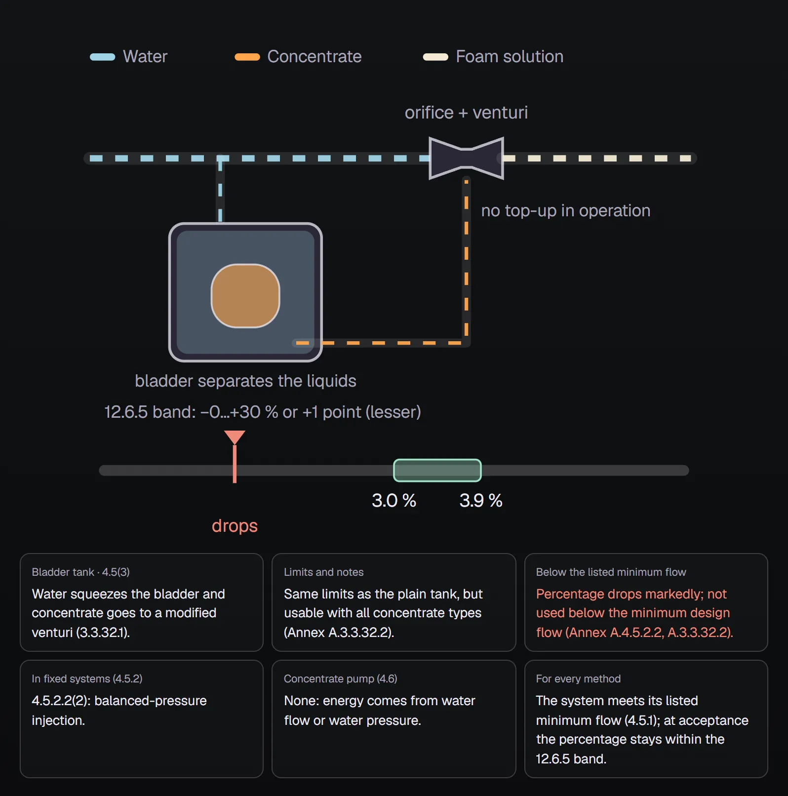
Who drifts which way when the flow drops?
Systems often run below design flow, for example with only a few heads open. Annex A describes how the methods drift:
| Method | Below the listed minimum flow | Source |
|---|---|---|
| Pressure tank, with or without bladder | Percentage drops markedly; not to be used below the minimum design flow | Annex A.4.5.2.2, Annex A.3.3.32.2 |
| Balanced pressure with a pump | Higher than anticipated per Annex A.4.5.2.2; lower than required per Annex A.4.5.1 and A.12.9.4(3) | Annex A.4.5.2.2, A.4.5.1, A.12.9.4(3) |
| In-line balanced or positive pressure | Percentage rises above design; the Annex treats this as desirable for closed systems with only a few sprinklers open | Annex A.4.5.1, A.12.9.4(4) |
| Vacuum induction (eductor) system | Needs a fixed discharge flow matching the inductor; supply and back pressure are critical and the percentage can vary; deluge only | Annex A.12.9.4(1) |
| Direct injection, water motor | NFPA 11 describes no low-flow behaviour; follow the listing | — |
The Annex does not speak with one voice here. For pump-type balanced pressure, Annex A.4.5.2.2 says "higher" while Annex A.4.5.1 and A.12.9.4(3) say "lower". What binds is the mandatory text: the proportioning system must meet its listed minimum flow (4.5.1). The real task is therefore to find the smallest flow the system will actually run at and select the proportioner for it. Some alcohol-resistant foam proportioners need a much higher minimum flow to proportion correctly (Annex A.4.5.1); for balanced-pressure systems below the minimum, the Annex points to a smaller proportioner or an in-line balanced-pressure system.
Which method for a fixed system? (4.5.2)
For fixed systems, balanced-pressure and positive-pressure injection are the preferred ways of putting concentrate into the water in the supply piping (4.5.2.1). Balanced-pressure injection takes one of four forms (4.5.2.2): pump with metering orifice and balancing valve, bladder pressure tank, in-line balanced pressure, or a pump discharging through an orifice straight into the riser at a set pressure margin. Three other listed methods are permitted (4.5.2.3): balanced positive-pressure injection that varies pump output with water flow while holding the percentage, around-the-pump proportioners and in-line eductors.
The self-educting nozzle, the coupled water-motor pump and direct injection appear in the 4.5 list but are not named in the 4.5.2 subclauses. Where orifices are used, the exposed tab or nameplate must permanently show the orifice diameter and, if flow characteristics depend on it, the flow direction (4.5.2.4). Deck foam systems on ships are proportioned by balanced pressure with a dedicated concentrate pump (11.12.1).
The extra burden of pump-based methods (4.6)
Pump-type balanced pressure, in-line balanced pressure, direct injection and the water-motor method all depend on a concentrate pump. Its rated capacity must cover the maximum system demand (4.6.2.1), and its discharge pressure at design flow must exceed the highest water pressure that can occur at the injection point (4.6.2.2). It must also deliver the actual flow at the highest proportioning rate permitted by 12.6.5 (4.6.8). Our own example: at 2000 L/min of solution, a 3 percent concentrate nominally needs 60 L/min; at the 12.6.5 ceiling of 3.9 percent that becomes 78 L/min, and the pump has to manage it.
A pump able to overpressurise the system needs relief from discharge to supply, and overpressure must not exceed the working pressure of the concentrate piping (4.6.3, 10.1.1, 10.1.2). The Annex notes these pumps are generally positive displacement and that centrifugal pumps may not suit high-viscosity concentrates (Annex A.4.6). Eductor methods, pressure tanks and around-the-pump proportioners need no separate concentrate pump; they take their energy from the water flow.
Acceptance and testing
- A discharge test records static and residual water pressure, actual discharge rate, consumption of foam-producing material and solution concentration (12.6.3).
- Concentration is measured by digital refractometer, digital conductivity, listed digital flowmeters or another means acceptable to the AHJ (12.6.2).
- The proportioning system may be tested by a listed or approved method that does not discharge concentrate (12.6.4).
- The Annex explains that listing tests establish the minimum and maximum flow of every proportioner size at full scale, and check that each concentrate proportions at its minimum storage temperature to at least 85 percent of the ambient-temperature result (Annex A.12.9.4).
For test and maintenance detail see NFPA 11 acceptance tests; to work out solution flow and concentrate demand for your own project use the NFPA 11 design criteria calculator and the foam-water sprinkler calculator.
Selection checklist
- What are the smallest and largest flows the system can really run at, and does the proportioner's listed range cover them (4.5.1)?
- Closed-head or open-head? An in-line eductor suits open-head or deluge systems only (Annex A.4.5.2.3(3)).
- Are concentrate and proportioner listed together (4.1.2)? Alcohol-resistant concentrates may need a higher minimum flow (Annex A.4.5.1).
- If the method uses a pump, do capacity, discharge pressure and relief meet 4.6?
- If you chose a pressure tank, does the supply calculation reflect that it cannot be topped up during a fire (Annex A.3.3.32.2)?
Frequently Asked Questions
How many foam proportioning methods does NFPA 11 recognise?
Seven: self-educting nozzle, in-line eductor, pressure proportioner (with or without bladder), around-the-pump proportioner, direct injection variable output pump, coupled water-motor driven pump and balanced pressure pump-type proportioner (4.5).
Why is a bladder tank a problem at low flow?
Annex A.4.5.2.2 says diaphragm or bladder tank systems proportion at a markedly reduced percentage at low flow and should not be used below their minimum design flow. They also cannot be topped up during a fire (Annex A.3.3.32.2).
Can an in-line eductor serve a sprinkler system?
Annex A.4.5.2.3(3) recommends in-line eductors only for open-head or deluge systems. Annex A.12.9.4(1) adds that vacuum induction needs a fixed discharge flow and is limited to deluge systems.
What is the acceptance tolerance on concentration?
Minus 0 to plus 30 percent of the listed concentration, or plus 1 percentage point, whichever is less (12.6.5). For 3 percent concentrate that is 3.0–3.9 %, for 6 percent 6.0–7.0 %.
Why does suction pressure matter for an around-the-pump proportioner?
Annex A.3.3.28 says pump suction pressure must be essentially zero gauge or on the vacuum side. Even a small positive pressure can cut the concentrate drawn in or push water back through the eductor into the container.

SprinkCalc — Fire Sprinkler Design Across Three Standards
SprinkCalc covers hazard classification, design density and area, K-factor selection, water demand and hydraulic calculations for NFPA 13, FM Global and BS EN 12845 in a single iOS app, and exports a professional PDF report.
Download SprinkCalc on the App Store
MEP Calc — 110+ Engineering Calculators
MEP Calc bundles 110+ engineering modules in one iOS app: 21 fire calculations plus heating, cooling, HVAC, plumbing, steam and natural gas.
Download MEP Calc on the App StoreNFPA 11-2024, Standard for Low-, Medium-, and High-Expansion Foam: 3.3.4, 3.3.4.1 (p. 11-10); 3.3.24.2, 3.3.26–3.3.28, 3.3.32.1–3.3.32.2 (pp. 11-12, 11-13); 4.1.2 (p. 11-13); 4.5–4.6.3 (p. 11-15); 4.6.4–4.6.9 (p. 11-16); 10.1 (p. 11-46); 11.12.1 (p. 11-50); 12.6.2–12.6.5 (p. 11-51); Annex A.3.3.4, A.3.3.4.1 (p. 11-58); Annex A.3.3.24.2–A.3.3.26.3 (p. 11-62); Annex A.3.3.28 (p. 11-63); Annex A.3.3.32.2 (pp. 11-67, 11-68); Annex A.4.5.1, A.4.5.2.2 (p. 11-70); Annex A.4.5.2.3(3), A.4.6 (p. 11-71); Annex A.12.9.4 (pp. 11-106, 11-107). Annex A is explanatory; the binding text is the standard itself and the decision of the authority having jurisdiction.