When the power fails, the energy to start a diesel fire pump is in its batteries. NFPA 20-2025 covers battery units, capacity, loads, location and recharging in 11.2.7.2, and the battery charger in 12.5 and 12.6. Reasons are taken only from Annex A and the NFPA 20 Handbook (2022) commentary.
In short: Each engine has two battery units, A and B (11.2.7.2.1.1). Each maintains the manufacturer’s recommended cranking speed at 40 °F (4 °C) for six consecutive cycles of 15 s cranking and 15 s rest (11.2.7.2.1.4, 11.2.7.2.1.5); together, without ac charging, they carry 72 hours of standby load followed by six cycles (11.2.7.2.1.6). Continuous standby load is no more than 0.5 A each for engine, controller and pump room equipment, 1.5 A in total (11.2.7.2.3.2). Recharging is by two means: the engine alternator and an automatic charger to 12.6 (11.2.7.2.5).
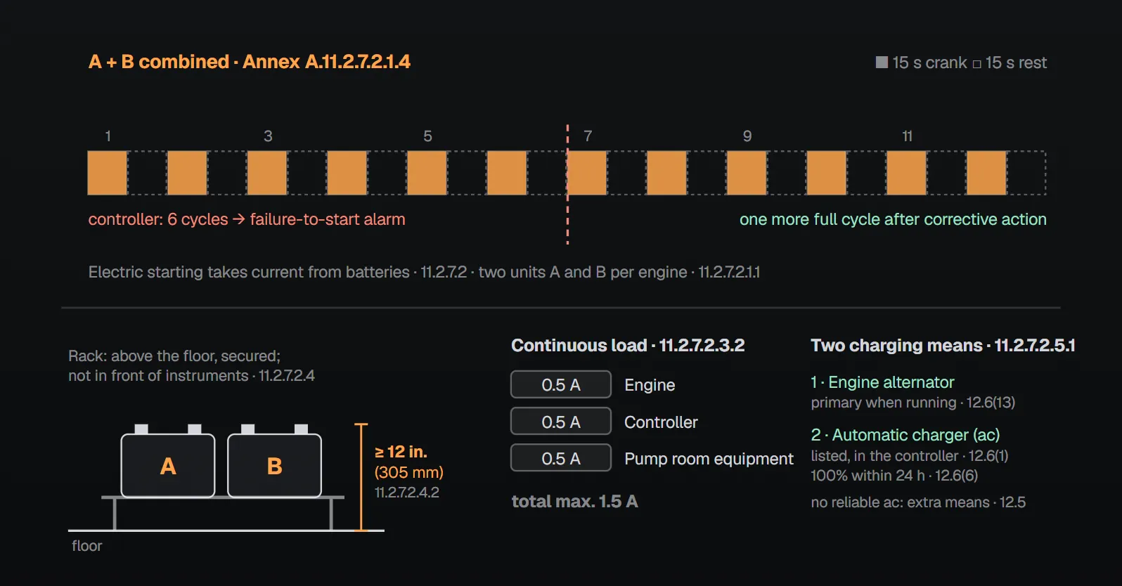
Battery units and capacity
The engine has a reliable starting device; with electric starting, current comes from storage batteries (11.2.7.1, 11.2.7.2).
| Item | Rule | Section |
|---|---|---|
| Number of units | Two storage battery units per engine: A and B | 11.2.7.2.1.1 |
| Delivery condition | Flooded lead-acid in moist or dry charge with electrolyte in a separate container; VRLA completed and charged | 11.2.7.2.1.2 |
| Other battery types | Nickel-cadmium or others permitted if they meet the engine maker’s requirements and charger voltages are coordinated to them | 11.2.7.2.1.3 |
| Unit A | Recommended cranking speed at 40 °F (4 °C) for 6 consecutive cycles (15 s cranking + 15 s rest) | 11.2.7.2.1.4 |
| Unit B | Same requirement | 11.2.7.2.1.5 |
| A + B combined | By calculation: the loads of 11.2.7.2.3 for 72 hours, then 6 cycles, without ac charging | 11.2.7.2.1.6 |
Per Annex A.11.2.7.2.1.4, A and B together cover 12 cycles: the controller completes six, stops and sends the failure-to-start alarm; the remaining capacity allows another full cycle after the operator has taken corrective action. Annex A.11.2.7.2.1.6 says the 72-hour requirement applies to new batteries and some degradation is expected with age.
Battery isolation
- An engine with one cranking motor has a main battery contactor between each battery and the cranking motor; it is listed for fire pump driver service, rated for cranking motor current and capable of manual mechanical operation (such as a spring-loaded, over-center operator) if the controller circuit fails (11.2.7.2.2.1).
- An engine with two cranking motors has one dedicated to each battery; each meets the single-motor cranking requirements and has an integral solenoid relay operated by the controller plus a mechanical switch on the engine panel for controller circuit failure (11.2.7.2.2.2).
Annex A.11.2.7.2.2 notes that manual operation of the contactor bypasses all control circuit wiring in the controller. Per the Handbook (2022), the contactors are normally open and keep the two units isolated so each stays fully charged.
Loads
Nonessential loads are not powered from the starting batteries (11.2.7.2.3.1). Essential loads, namely the engine, controller and all pump room equipment, do not exceed 0.5 A each, 1.5 A in total, on a continuous basis (11.2.7.2.3.2); the ECM also draws no more than 0.5 A while the engine is stopped (11.2.4.2.7.2). Per Annex A.11.2.4.2.7.1, with the batteries in float during standby it is actually the chargers that supply this current. The Handbook (2022) says the loads are limited because charger output is limited.
Battery location and cables
- Batteries are rack supported above the floor, secured against displacement, and away from excessive temperature, vibration, mechanical injury or flooding (11.2.7.2.4.1).
- Current-carrying parts are at least 12 in. (305 mm) above the floor (11.2.7.2.4.2).
- They are readily accessible, not in front of engine-mounted instruments and controls, and racks and location meet NFPA 70 (11.2.7.2.4.3–11.2.7.2.4.5).
- Battery cables are sized to the engine maker’s recommendations, considering the length needed for the battery location (11.2.6.3.1).
Annex A.11.2.7.2.4 recommends batteries at the side of and level with the engine to keep battery-to-starter leads short. Per the Handbook (2022), every cable in the circuit (positive, negative, jumper, contactor-to-starter, ground) counts toward the length.
Recharging and the charger
Batteries are recharged two ways: the generator or alternator furnished with the engine, and an automatically controlled charger to 12.6 fed from an ac source (11.2.7.2.5.1–11.2.7.2.5.3). If ac power is not available or not reliable, another charging method is provided in addition to the alternator (12.5). Per Annex A.11.2.7.2.5, a single charger that automatically alternates between the two batteries may be used.
| Charger requirement | Section |
|---|---|
| Listed for fire pump service and part of the diesel fire pump controller | 12.6(1) |
| Additional listed chargers may be installed outside the controller for capacity or redundancy | 12.6(2) |
| Semiconductor rectifier | 12.6(3) |
| For lead-acid, charging rate drops automatically below 500 mA at full charge | 12.6(4) |
| At rated voltage, charges a fully discharged battery without damage | 12.6(5) |
| Restores 100% of reserve capacity or ampere-hour rating within 24 hours | 12.6(6) |
| Marked with the largest battery capacity it can recharge to 12.6(6) | 12.6(7) |
| Voltage and charging current of each battery readable on the controller exterior within ±2% | 12.6(8) |
| Not damaged and no blown fuses during cranking | 12.6(9) |
| Charges automatically at the maximum rate when the battery state requires | 12.6(10) |
| Where not connected through a control panel, indicates loss of current output on the load side of the dc overcurrent device | 12.6(11) |
| Remains in float, or switches from equalize to float, while batteries are under load | 12.6(12) |
| The alternator is the primary means of charging when the engine runs | 12.6(13) |
Hydraulic starting (briefly)
With hydraulic starting the accumulators are protected; without starting aids other than 11.2.8.2, the engine carries full rated load within 20 seconds of cranking with intake air, room and starting equipment at 32 °F (0 °C) (11.2.7.3.1–11.2.7.3.4). As the only or primary system it provides at least 12 cycles of at least 15 seconds (180 s total) from two equal accumulator systems: the first 6 attempts automatic and alternating, the next 6 manual (11.2.7.3.11–11.2.7.3.11.3). As a secondary system 6 cycles (90 s) suffice: 3 automatic, 3 manual (11.2.7.3.12). Air starting has its own article: air-starting engine controllers.
Why?
- 40 °F and double capacity: Per the Handbook (2022), battery output falls with temperature, hence 40 °F (4 °C). Two units leave capacity for another full cycle after a complete cranking cycle; the 15-second rest keeps the starter from overheating on single-starter engines.
- 72 hours: The Handbook (2022) says the requirement considers a 72-hour blackout, after which one full cycle (six attempts) must remain after a continuous 1.5 A load; the double cranking capacity does not apply to this calculation.
- Arrival on site: Per Annex A.11.2.7.2.1.2, batteries that will sit on site for a long time should be flooded, dry-charged, and filled and charged just before use; VRLA batteries arrive charged just before use. Per the Handbook (2022), electrolyte is added and batteries charged for at least 24 hours before in-service testing.
Checklist
- Two battery units (A, B), each selected for 6 cycles at 40 °F (4 °C)? (11.2.7.2.1)
- 72 hours + 6 cycles calculated, standby load not over 1.5 A? (11.2.7.2.1.6, 11.2.7.2.3.2)
- Current-carrying parts at least 12 in. (305 mm) above the floor, instruments unobstructed? (11.2.7.2.4)
- Main battery contactors or dual starters, with manual cranking? (11.2.7.2.2)
- Charger listed, in the controller and able to restore 100% in 24 hours? (12.6)
Frequently Asked Questions
How many batteries does a diesel fire pump engine have?
Two battery units, A and B (NFPA 20-2025 11.2.7.2.1.1). Each alone covers six cranking cycles at 40 °F (4 °C) (11.2.7.2.1.4, 11.2.7.2.1.5).
How long is one cranking cycle?
15 seconds of cranking and 15 seconds of rest; each unit maintains the recommended cranking speed for six consecutive cycles (11.2.7.2.1.4). Per Annex A.11.2.7.2.1.4, A and B together cover 12 cycles.
How long must the batteries last in a power outage?
A and B combined carry the loads of 11.2.7.2.3 for 72 hours without ac charging and then provide six more cranking cycles; sizing is by calculation (11.2.7.2.1.6).
How much continuous current may be drawn from the batteries?
0.5 A each for engine, controller and pump room equipment, 1.5 A total (11.2.7.2.3.2). Nonessential loads are not powered from the starting batteries (11.2.7.2.3.1).
What are the key battery charger requirements?
It is listed for fire pump service and part of the diesel controller, restores 100% of battery capacity within 24 hours, and voltage and charging current are readable outside the controller within ±2% (12.6(1), 12.6(6), 12.6(8)).

SprinkCalc — Fire Sprinkler Design Across Three Standards
SprinkCalc covers hazard classification, design density and area, K-factor selection, water demand and hydraulic calculations for NFPA 13, FM Global and BS EN 12845 in a single iOS app, and exports a professional PDF report.
Download SprinkCalc on the App Store
MEP Calc — 110+ Engineering Calculators
MEP Calc bundles 110+ engineering modules in one iOS app: 21 fire calculations plus heating, cooling, HVAC, plumbing, steam and natural gas.
Download MEP Calc on the App StoreNFPA 20-2025, Standard for the Installation of Stationary Pumps for Fire Protection: 11.2.4.2.7.2; 11.2.6.3.1; 11.2.7.1–11.2.7.2.5.3; 11.2.7.3.1–11.2.7.3.12; 12.5; 12.6(1)–(13); Annex A.11.2.4.2.7.1, A.11.2.7.2.1.2, A.11.2.7.2.1.4, A.11.2.7.2.1.6, A.11.2.7.2.2, A.11.2.7.2.4, A.11.2.7.2.5 (explanatory). NFPA 20 Handbook 2022 commentary: Sections 11.2.4.2.7, 11.2.6.3, 11.2.7.