A diesel fire pump engine holds its own speed, shuts itself down on overspeed and reports its faults to the controller. NFPA 20-2025 covers this in 11.2.4 (speed controls), 11.2.5 (instrumentation) and 11.2.6 (wiring). Reasons are taken only from Annex A and the NFPA 20 Handbook (2022) commentary.
In short: The governor holds engine speed within 10% between pump shutoff and maximum load (11.2.4.1.1); the engine reaches rated speed within 20 seconds (11.2.4.1.4). An engine with an electronic control module (ECM) has a permanently wired alternate ECM (11.2.4.2.1), and the ECM never intentionally reduces rated power (11.2.4.2.4). The overspeed device shuts the engine down at 10–20% above rated speed and is reset manually (11.2.4.4.2). Oil pressure, temperature and cooling water conditions are signaled to the controller, and each signal can be tested from the engine (11.2.4.4).
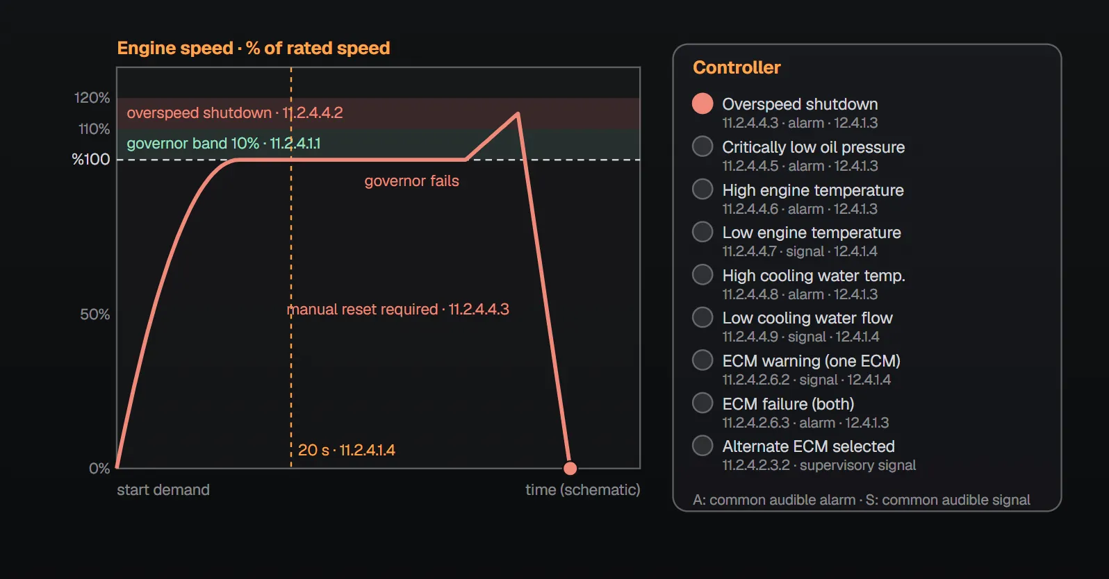
Speed governor
- The governor can regulate engine speed within a range of 10% between pump shutoff and maximum load (11.2.4.1.1).
- It is field adjustable and set and secured to maintain rated pump speed at maximum pump load (11.2.4.1.2).
- Mechanical fuel injection engines with a mechanical governor may use an electric-actuated speed control override for speed control tighter than 10%, provided 11.2.4.1.1 is still met if any part of that actuator system fails (11.2.4.1.3).
- The engine accelerates to rated output speed within 20 seconds (11.2.4.1.4).
The Handbook (2022) calls the speed loss from churn to 150% flow droop: the greater the droop, the greater the pressure increase at churn. The electric actuator does not have the redundancy of full electronic injection; on failure the engine may enter noncomplying speed regulation.
Electronic control module (ECM)
| Item | Rule | Section |
|---|---|---|
| Alternate ECM | Permanently mounted and wired; full rated power on primary ECM failure | 11.2.4.2.1 |
| Voltage protection | Against transient voltage spikes and reverse dc current | 11.2.4.2.2 |
| Selector switch | Hand/automatic, no off position; automatic transfer on failure in auto, manual in hand | 11.2.4.2.3.1 |
| Supervision | Visual indicator on the engine panel and supervisory signal to the controller when on the alternate ECM | 11.2.4.2.3.2 |
| Contacts, enclosure, mounting | Contacts rated for minimum and maximum current and voltage; NEMA Type 2 dripproof enclosure; engine mounted and isolated from vibration | 11.2.4.2.3.3–11.2.4.2.3.5 |
| No derating | The ECM or its sensors never intentionally reduce rated power output | 11.2.4.2.4 |
| Sensor redundancy | Every sensor affecting rated power has an automatic redundant sensor | 11.2.4.2.5 |
| Power supply | In standby the ECM is powered from engine batteries or chargers; not more than 0.5 A while the engine is not running | 11.2.4.2.7.1, 11.2.4.2.7.2 |
Annex A.11.2.4.2.4 explains that an ECM may be designed to cut power to protect the engine under stress such as high cooling water temperature; this is not permitted on fire pump engines. Handbook (2022) commentary: it is preferable for the engine to run as long as possible, even at risk, to protect the facility.
Variable speed pressure or suction limiting
Where provided, this control is listed for fire pump service and limits discharge or suction pressure by reducing speed; it does not replace the governor, and on its failure the engine runs at rated speed on the governor (11.2.4.3.2–11.2.4.3.4). A ½ in. (12.7 mm) sensing line runs to the engine: for pressure limiting from between the discharge flange and the discharge check valve, for suction limiting from the pump inlet flange; where sediment could enter, a drop-down trap and cleanout are installed (11.2.4.3.5.2–11.2.4.3.5.5). Stable pressure (±10%) is reached within 20 seconds of a start demand and restabilizes within 20 seconds after a flow change (11.2.4.3.6, 11.2.4.3.6.1). General line rules: pressure sensing line.
Overspeed and engine signals
The overspeed device shuts down the engine in a range of 10–20% above rated speed and is manually reset; the controller cannot be reset until the device is manually returned to normal; the switch and circuitry shutdown function can be verified (11.2.4.4.1–11.2.4.4.4).
| Condition | At the controller | Section |
|---|---|---|
| Shutdown from overspeed | Alarm (12.4.1.3) | 11.2.4.4.3 |
| Critically low lubricating oil pressure | Alarm (12.4.1.3) | 11.2.4.4.5, 11.2.4.4.5.1 |
| High engine temperature | Alarm (12.4.1.3) | 11.2.4.4.6, 11.2.4.4.6.1 |
| Low engine temperature | Signal (12.4.1.4) | 11.2.4.4.7, 11.2.4.4.7.1 |
| High cooling water temperature (set by the engine maker, coordinated with the heat exchanger water supply) | Alarm (12.4.1.3) | 11.2.4.4.8, 11.2.4.4.8.1 |
| Low cooling water flow | Signal (12.4.1.4) | 11.2.4.4.9, 11.2.4.4.9.1 |
| ECM warning: one ECM failed | Signal (12.4.1.4) | 11.2.4.2.6.2 |
| ECM failure: both ECMs failed | Alarm (12.4.1.3) | 11.2.4.2.6.3 |
| Fuel injection trouble, low fuel pressure, any primary sensor failure | Common supervisory signal | 11.2.4.2.6.1 |
12.4.1.3 conditions give separate visible indicators and a common audible fire pump alarm; 12.4.1.4 conditions give separate visible indicators and a common audible signal. Each signal has a test means on the engine, with test instructions in the engine manual (e.g. 11.2.4.4.5.2). A speed-sensitive switch signals engine running and crank termination; its power is not taken from the engine generator or alternator (11.2.4.5.1, 11.2.4.5.2). Controller alarm and silencing rules: diesel engine drive controllers.
Instruments and wiring
- All engine instruments are on a panel secured to the engine or inside an engine base plate–mounted controller; the panel is not used as a junction box or conduit for any ac supply (11.2.5.1.1, 11.2.5.1.2).
- A tachometer shows rpm, including zero, at all times; total run time is recorded; a digital display may be blank when the engine is not running (11.2.5.2.1–11.2.5.2.3).
- An oil pressure gauge and a coolant temperature gauge reading at all times are provided; the type of trouble in 11.2.4.2.6 is indicated on the engine (11.2.5.3–11.2.5.5).
- Controller wires are harnessed or flexibly enclosed and land in an engine junction box on terminals numbered to match the controller; engine wiring is sized for continuous duty (11.2.6.1.1, 11.2.6.1.2). Field interconnections use stranded wire, with dc interconnections and any ac supply in separate conduits (11.2.6.2.1, 11.2.6.2.2).
Why?
- Overspeed: Per the Handbook (2022), if the governor fails or the engine draws uncontrolled fuel such as a gaseous fuel through the air cleaner, speed rises; discharge pressure rises with speed and piping can be damaged. For the main relief valve see main relief valve location.
- Alternate ECM and supervision: The Handbook (2022) says the supervisory signal on transfer to the alternate ECM calls personnel to the room, and both ECMs should be kept in working order.
- ac/dc separation: Per the Handbook (2022), mixing ac and dc circuits in the same conduit or enclosure risks cross talk between circuits.
- Signal tests: The Handbook (2022) notes these features are tested at commissioning and that testing them annually is good practice.
Checklist
- Is the governor within the 10% band, set and secured at rated speed for maximum load? (11.2.4.1)
- Does the engine reach rated speed within 20 seconds? (11.2.4.1.4)
- On an ECM engine: alternate ECM, selector switch with no off position and supervisory signal? (11.2.4.2)
- Does overspeed shut down within 10–20% and require manual reset? (11.2.4.4.2)
- Is each signal tested from the engine and shown correctly at the controller? (11.2.4.4)
Frequently Asked Questions
What range does the governor on a diesel fire pump engine work in?
It holds engine speed within 10% between pump shutoff (churn) and maximum load, and is set and secured to maintain rated speed at maximum load (NFPA 20-2025 11.2.4.1.1, 11.2.4.1.2).
At what speed does the overspeed device shut the engine down?
In a range of 10–20% above rated speed, with manual reset; the controller cannot be reset until the device is manually reset (11.2.4.4.2, 11.2.4.4.3).
What happens if one ECM fails?
The permanently wired alternate ECM takes over and the engine delivers full rated power (11.2.4.2.1). A single ECM failure gives a 12.4.1.4 signal at the controller; failure of both gives a 12.4.1.3 alarm (11.2.4.2.6.2, 11.2.4.2.6.3).
Can the ECM derate the engine to protect it?
No. The ECM or its sensors never intentionally reduce rated power (11.2.4.2.4). Annex A.11.2.4.2.4 says power-reducing engine safeguards, for example on high cooling water temperature, are not permitted on fire pump engines.
Which engine conditions are alarms at the controller?
Overspeed shutdown, critically low oil pressure, high engine temperature, high cooling water temperature and failure of both ECMs are 12.4.1.3 alarms; low engine temperature, low cooling water flow and a single ECM failure are 12.4.1.4 signals (11.2.4.4, 11.2.4.2.6).

SprinkCalc — Fire Sprinkler Design Across Three Standards
SprinkCalc covers hazard classification, design density and area, K-factor selection, water demand and hydraulic calculations for NFPA 13, FM Global and BS EN 12845 in a single iOS app, and exports a professional PDF report.
Download SprinkCalc on the App Store
MEP Calc — 110+ Engineering Calculators
MEP Calc bundles 110+ engineering modules in one iOS app: 21 fire calculations plus heating, cooling, HVAC, plumbing, steam and natural gas.
Download MEP Calc on the App StoreNFPA 20-2025, Standard for the Installation of Stationary Pumps for Fire Protection: 11.2.4.1.1–11.2.4.1.4; 11.2.4.2.1–11.2.4.2.7.2; 11.2.4.3.2–11.2.4.3.6.1; 11.2.4.4.1–11.2.4.4.9.2; 11.2.4.5.1, 11.2.4.5.2; 11.2.5.1.1–11.2.5.5; 11.2.6.1.1–11.2.6.2.2; 12.4.1.3, 12.4.1.4; Annex A.11.2.4.2, A.11.2.4.2.4 (explanatory). NFPA 20 Handbook 2022 commentary: Sections 11.2.4–11.2.6.